
By the Yzng Trong International engineering team — we design and manufacture 316 stainless steel vacuum ball valves and KF-flanged components in Taiwan, and we answer these sizing questions from buyers every week.
Last updated: 2026-07-03
Key Takeaways
- KF and NW are two names for the same flange. A KF50 flange and an NW50 flange are identical and fully interchangeable.
- The standard behind both names is ISO-KF, defined in ISO 2861 and DIN 28403, covering nominal sizes DN10 to DN50.
- You can identify any KF flange size in seconds by measuring its outside diameter: 30 mm means KF10 or KF16, 40 mm means KF25, 55 mm means KF40, 75 mm means KF50.
- A KF connection seals with an O-ring on a centering ring, closed by a hand-tightened clamp. No bolts, no tools.
- With elastomer seals, KF connections work from atmosphere down to about 1 × 10⁻⁸ hPa, which covers most industrial vacuum systems.
What Is a KF Flange?
A KF flange is a quick-release vacuum flange that seals with an elastomer O-ring and a hand-tightened clamp instead of bolts. If you have ever specified a fitting as NW25, QF40, or DN50 ISO-KF, you were describing the same family of parts: the naming is different, the hardware is not.
The letters KF come from the German Klein Flansch, meaning “small flange”. According to the Kurt J. Lesker Company’s KF flange technical notes, the KF designation was adopted by ISO, DIN, and Pneurop, and the same flange is also called QF, NW, and occasionally DN. That is four names for one part, which is exactly why so many engineers search for the difference between KF and NW flanges before placing an order.
This guide settles the naming question first, then gives you the full KF size chart, explains how the clamp seal actually works, and shows how to match vacuum valves and fittings to each size. We work with these connections daily on our own 316 stainless steel vacuum valve line, so the recommendations below come from parts we build and test, not from a catalog we resell.
KF vs NW: Are They the Same Flange?
Yes. KF and NW describe the same ISO-KF flange, and parts marked with either name mate with each other without adapters. There is no dimensional difference, no pressure-rating difference, and no seal difference. If your pump port says NW50 and your valve says KF50, they bolt together — or rather, they clamp together, because that is the point of the design.
Where does each name come from?
Each name reflects a different tradition, not a different part. KF is the German abbreviation for Klein Flansch. NW stands for Nennweite, German for “nominal width”, so NW50 simply reads “nominal size 50 mm”. QF means Quick Flange, a name common in older American catalogs. DN is the international nominal-diameter prefix used across piping standards, so DN50 ISO-KF is the most formally correct way to write the same size. European pump makers tend to print DN or NW on their spec sheets, while American component houses lean on KF or QF. Taiwanese and Japanese equipment documentation mixes all four freely, which is how a single vacuum line ends up with three names for one flange in its bill of materials.
Which standards define the KF flange?
Two documents matter. Internationally, ISO 2861:2020, Vacuum technology — Dimensions of clamped-type quick-release couplings, fixes the dimensions of the flange, the O-ring, and the centering carrier. In Germany, DIN 28403 covers the same clamped quick-release couplings for rough, medium, and high vacuum. The two standards are harmonized in practice: a flange machined to either document mates with the other. This is why interchangeability across brands is taken for granted in vacuum work — the standard, not the manufacturer, owns the interface.
What should you write on a purchase order?
Write the size once in the form your supplier uses, and add one clarifier: “ISO-KF”. A line like “NW50 (ISO-KF / KF50) clamp flange” removes every possible misreading for a few extra characters. What you should not do is write only “DN50”, because DN50 without the ISO-KF qualifier can also mean a bolted pipe flange in water or steam service — a completely different part. We name our own vacuum products with both designations, for example our pneumatic ball valve in NW50 (ISO-KF) clamp-end configuration, precisely so the order desk and the fab engineer read the same thing.
How Does a KF Flange Seal Work?
A KF connection seals through three parts: two identical flange faces, one elastomer O-ring carried on a metal centering ring, and one clamp that presses the faces together. Tighten the clamp’s wing nut by hand and the joint is vacuum-tight; open it and the line comes apart in seconds. That tool-free serviceability is the reason the design has dominated small-bore vacuum plumbing for decades.
The centering ring and O-ring
The centering ring positions the O-ring exactly on the sealing axis and stops it from being crushed or extruded when the clamp closes. Both flange faces are genderless — there is no male or female side — so any two same-size KF parts join in any orientation. Rings come in different body materials and elastomers; a stainless steel carrier is the default choice where corrosion or frequent cleaning is a concern, which is why our own KF/NW centering rings (KF16 to KF50) use an SS304 body. The O-ring is the consumable in this system: inspect it every time the joint is opened and replace it at the first sign of flattening or cracking.
The clamp
The aluminum hinged clamp does the mechanical work. Closing it wedges the two flange chamfers toward each other, compressing the O-ring by a controlled amount. Hand-tight is correct torque: the geometry bottoms out at the right compression, so reaching for a wrench adds nothing except a deformed clamp. For sizes KF10 through KF50 one hand is enough, which matters when you are reconfiguring a pump cart or swapping a gauge in a crowded tool bay.
What vacuum levels can a KF connection handle?
With standard elastomer seals, KF connections are suitable from atmospheric pressure down to about 1 × 10⁻⁸ hPa, and they also tolerate moderate overpressure up to roughly 1,500 hPa absolute, according to the Pfeiffer Vacuum knowledge book on vacuum connections. With special metal seals the range extends below 1 × 10⁻⁹ hPa. Pfeiffer’s engineers add a caution worth quoting: detachable joints are a significantly more frequent source of potential leakage than welded joints, so a well-designed system uses as few demountable connections as it can get away with. In practice that means: clamp a KF joint where you genuinely need to open the line — at valves, gauges, traps, and pump ports — and weld the rest.
KF Flange Size Chart: KF10 to KF50
The fastest way to identify a KF flange size is to measure the flange outside diameter with calipers, because each size has a unique OD — except KF10 and KF16, which share a 30 mm OD and are told apart by the bore. The chart below covers the five standard sizes defined by ISO 2861.
| Designation | Equivalent names | Nominal bore (DN, mm) | Flange OD (mm) | Approx. matching tube size |
|---|---|---|---|---|
| KF10 | NW10, QF10, DN10 ISO-KF | 10 | 30 | ≈ 1/2 in |
| KF16 | NW16, QF16, DN16 ISO-KF | 16 | 30 | ≈ 3/4 in |
| KF25 | NW25, QF25, DN25 ISO-KF | 25 | 40 | ≈ 1 in |
| KF40 | NW40, QF40, DN40 ISO-KF | 40 | 55 | ≈ 1-1/2 in |
| KF50 | NW50, QF50, DN50 ISO-KF | 50 | 75 | ≈ 2 in |
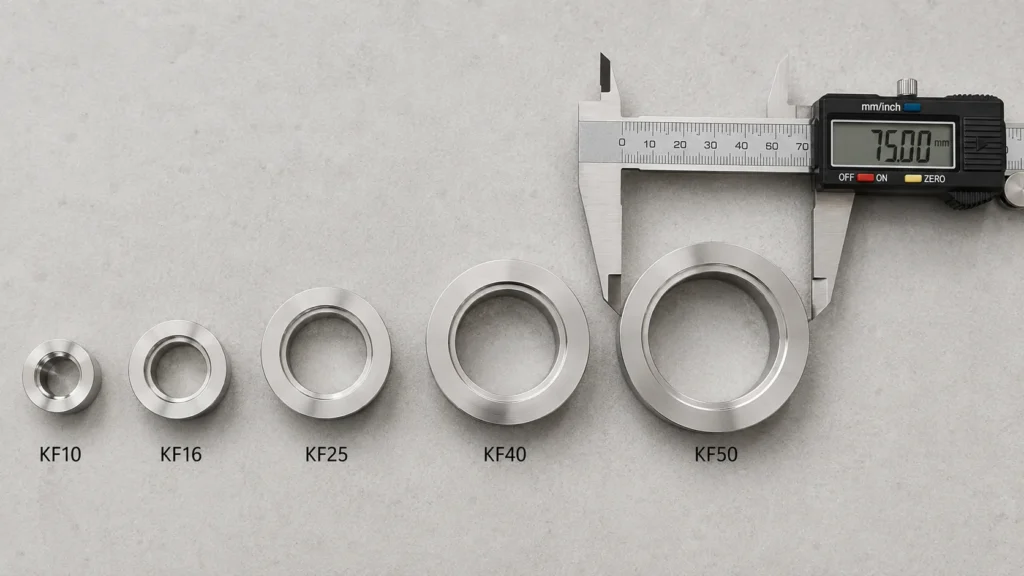
Tube equivalents are nominal: inch-based shops weld imperial tube to the flange stub, metric shops weld the matching DN tube, and both end up with the same interchangeable flange face. When a drawing calls out DN20 or DN32 you are looking at older German documentation; those intermediate sizes appear in some standards editions but are rarely stocked, and most systems jump straight from KF16 to KF25 and from KF25 to KF40.
How do I identify an unknown flange in the field?
Measure the OD first, then the bore. A 40 mm OD can only be KF25; a 75 mm OD can only be KF50. For the two 30 mm twins, a bore around 10 mm means KF10 and around 17 mm means KF16. Do not judge by the tube welded behind the flange — reducers and adapters make tube diameter an unreliable witness. Two minutes with calipers beats an afternoon of returns paperwork.
Why does everyone stock KF25 and KF50?
Because those two sizes bracket the flow needs of most small vacuum systems. KF16 and KF25 dominate gauge ports and instrument connections, while KF40 and KF50 carry foreline traffic between chambers and pumps. Our own sales data reflects the same split: KF25 and NW50 parts outsell the other sizes combined, which is why our three-piece manual vacuum valve covers NW16, NW25, NW40, and NW50 with one body design — stocking one valve family for every port on the tool is simpler than mixing brands per size.
Where Are KF Connections Actually Used?
KF hardware shows up wherever a vacuum system needs to come apart for service: pump forelines, gauge ports, vent and purge lines, and the instrument side of process chambers. The pattern across industries is consistent — the chamber itself may use larger ISO or CF flanges, but the plumbing around it runs on KF because technicians open those lines routinely.
In semiconductor and electronics facilities, KF sizes dominate the facility-side vacuum plumbing that supports process tools: roughing lines to dry pumps, abatement connections, and the isolation points in between. This is the environment our own valves are most often specified into, and the requirements there — 316 stainless wetted parts, clean assembly, quarter-turn isolation that a technician can verify at a glance — carry over to any high-purity plant; our semiconductor application overview covers that side in more depth. Analytical instruments are the second big user: mass spectrometers, electron microscopes, and surface-science tools hang their backing pumps and vent valves on KF16 and KF25 ports. Industrial coating, heat treatment, and freeze-drying round out the list, typically at KF40 and KF50 where pumping speed matters, with three-piece valves favored because those processes load the foreline with condensables that eventually demand a seat cleaning.
The common thread is serviceability under time pressure. When a coater is down, the maintenance window is measured in hours, and a line that opens by hand — valve out, seat swapped, valve back, clamp closed — is the difference between a same-shift recovery and a scheduled outage.
Aluminum, SS304, or 316: Which Material Where?
Match the material to the exposure, not to habit. KF clamps are almost universally aluminum, and that is fine: the clamp never touches process gas, so its job is mechanical, not chemical. Flanges, centering-ring carriers, and valve bodies are where material choice earns or costs money.
For flanges and carriers, stainless steel is the default in any plant that washes down equipment, runs corrosive ambient air, or simply wants one material standard across the site — an SS304 carrier like the one on our KF/NW centering rings covers those cases at minimal premium. For valve bodies and other wetted components, we build in ASTM 316. The deciding factor between 304 and 316 is not acidity in general but chloride exposure and pitting risk: 316’s molybdenum content specifically resists chloride-induced pitting, which is why coastal plants, facilities using chlorinated water treatment, and fabs with aggressive cleaning chemistries specify it. If your process and environment see no chlorides, 304 hardware performs honorably; if you cannot rule chlorides out, the price gap between the two grades is far smaller than the cost of replacing pitted parts.
One caution from the supplier side: do not mix material claims and assumptions when reselling or documenting a system. A flange stamped 304 next to a valve body in 316 is a perfectly good system — as long as the maintenance records say which is which.
How Does Temperature Limit a KF Connection?
The elastomer O-ring sets the temperature ceiling of every KF joint, because the metal parts outlast it by a wide margin. Standard nitrile (NBR) rings suit general-purpose service around room temperature and modest heat; fluoroelastomer (FKM) rings extend the working range meaningfully higher and resist a broader chemical set, which is why they are the usual upgrade for lines near hot pumps or mild bakeouts. Exact limits depend on the compound, so hold your supplier to the datasheet for the specific ring rather than a generic figure.
What a clamped elastomer joint cannot do is survive a true bakeout at the temperatures ultra-high vacuum work demands — that duty belongs to copper-gasket CF flanges, as the flange family comparison above showed. On the cold side, remember that our own pneumatic NW50 valve is rated -20°C to 80°C as a complete assembly: on any valve, the assembly rating — body, seats, seals, and actuator together — is the number that governs, and it is usually narrower than the bare flange hardware would suggest. When in doubt, rate the line by its weakest elastomer and note it on the P&ID, so the next engineer does not discover the limit empirically.
How Do You Assemble a KF Joint Correctly?
Correct assembly takes under a minute: inspect, center, clamp, hand-tighten. Most field leaks trace back to skipping the first step, so treat inspection as part of the procedure rather than an optional extra.
Step-by-step assembly
- Wipe both flange faces with a lint-free wipe. Any fiber, chip, or old elastomer fragment sitting on the sealing face becomes a leak channel.
- Inspect the O-ring on its centering ring. Replace it if it shows flats, nicks, cracking, or a shiny compression set; the ring is the only wearing part in the joint.
- Seat the centering ring in the recess of one flange. It should sit concentric without force.
- Bring the second flange face square onto the ring. The joint is genderless, so orientation does not matter.
- Close the hinged clamp around both flange chamfers and spin the wing nut down finger-tight. Stop there — the flange geometry limits O-ring compression to the design value.
How do you leak-check the joint afterwards?
For routine work, watch the system pump-down curve: a joint-level leak shows up as a pressure floor well above the system’s known base pressure. For diagnosis, spray a small amount of isopropyl alcohol or helium around the suspect clamp while watching the gauge or a leak detector — a responding signal localizes the fault. Nine times out of ten the fix is a fresh centering ring, not a new flange. If a joint keeps failing after ring replacement, check the flange faces for radial scratches from a dropped part or a screwdriver used as a lever; a scratched face is the one fault that does require replacing hardware.
What Comes After KF50? ISO-K, ISO-F, and CF
Above DN50, the clamp-and-O-ring concept stops scaling, and vacuum systems move to larger flange families. The comparison below shows where each family fits; the Lesker flange systems overview is a good deep-dive if you are mapping a whole system.
| Flange family | Typical size range | Seal | Closure | Typical service |
|---|---|---|---|---|
| ISO-KF (KF/NW) | DN10–DN50 | Elastomer O-ring on centering ring | Hand-tightened wing-nut clamp | Rough to high vacuum lines, gauges, forelines |
| ISO-K / ISO-F | DN63 and up | Elastomer O-ring on centering ring | Claw clamps (ISO-K) or bolted collar (ISO-F) | Large chamber ports, big roughing lines |
| CF (ConFlat) | DN16–DN250 | Copper gasket, knife-edge | Bolted | Ultra-high vacuum, bakeable systems |
The practical takeaway: KF is the connection you service weekly, ISO-K is the connection you open per project, and CF is the connection you hope to open once a year. The seal principle of ISO-K is identical to KF — same O-ring-on-carrier idea, bigger diameter, claw clamps instead of a single band — so skills transfer directly. We build valves for both interfaces, including an ISO100 manual vacuum ball valve on the ISO-K side, so mixed-flange systems can keep one valve supplier across sizes.
How Do You Choose Valves and Fittings for a KF Line?
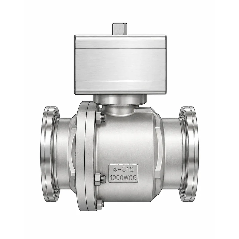
Choose by answering three questions in order: how often the valve cycles, whether it must fail to a safe position, and what the process gas demands of the seal materials. Size is already settled by the line itself — a KF25 line takes a KF25 valve — so selection is really about actuation and materials.
Manual or pneumatic?
Manual quarter-turn valves suit isolation points that change state a few times a day or less: pump service ports, vent lines, gauge isolation. Their advantage is zero support infrastructure — no air, no wiring. Once a valve cycles many times per shift, or sits behind an interlock, a rack-and-pinion pneumatic actuator earns its cost. Our NW50 pneumatic ball valve, for example, is offered double-acting or spring-return; the spring-return version drives the valve to its resting position on air loss, which is the standard way to make a vacuum isolation point fail-safe. For switching between two destinations — pump A and pump B, process and bypass — a 3-way vacuum ball valve with L-port or T-port replaces two 2-way valves and a tee.
What materials matter in the flow path?
Body and seal. Our vacuum valves use ASTM 316 stainless steel bodies with PTFE seats, a combination chosen for corrosion resistance and low outgassing in facility-side service. The same logic applies to the humble centering ring: the elastomer must match the gas chemistry and temperature, and the carrier should be stainless where washdown or corrosive ambients are involved. On facility gas and vacuum panels for semiconductor plants — an application we detail on our semiconductor ball valve page — 316 bodies are the default expectation, not an upgrade.
Serviceability: two-piece or three-piece?
A two-piece body is compact and economical; a three-piece body lets maintenance open the valve for seat replacement without cutting the line or disturbing the flanges on either side. On lines that see condensable loads or particulate — pump forelines in coating and heat-treatment service are the classic case — the three-piece construction pays for itself at the first rebuild. This is the reason our NW16–NW50 manual vacuum valve is built three-piece as standard.
Which KF Accessories Should You Keep in Stock?
A short shelf of consumables keeps a KF system serviceable on the day something fails, and the whole list fits in one small parts drawer. Centering rings top the list: stock at least two spare rings per size in use, because every opened joint is a candidate for a fresh O-ring, and rings are the cheapest insurance in vacuum work. Clamps rarely wear out, but one spare per size covers the clamp that walks away during a rebuild.
Blank flanges deserve more respect than they get. A blanked-off port lets you isolate a section for troubleshooting, cap an unused instrument port properly, or keep a dismounted line clean during storage — taping over an open KF port is how fibers end up on sealing faces. Adapters between KF sizes (a KF40-to-KF25 reducer, for example) and KF-to-hose transitions let one pump cart serve tools with different port sizes; buy them for the specific transitions on your floor rather than a generic assortment, since unused adapters have a way of multiplying in drawers.
The buying rule we give customers is simple: standardize the consumables, then the sizes. Choosing one carrier material and one elastomer for all centering rings — stainless carriers if any line sees washdown or corrosive ambient air — means any ring on the shelf fits any joint of that size in the plant, and nobody has to match part numbers during a Friday-evening repair. Our own pipe fittings range carries the KF16–KF50 centering rings alongside the threaded stainless fittings that the pressurized side of the same facility runs on, so one order covers both halves of the utility panel.
Five Common Mistakes When Specifying KF Connections
Most KF problems are ordering problems, not engineering problems. These are the five we see most often from the supplier side of the counter.
First, treating KF and NW as different parts and paying for an “adapter” that is really two clamps and a straight nipple. They are the same flange; nothing needs adapting. Second, writing bare “DN50” on a requisition and receiving a bolted water-pipe flange instead of a vacuum part — always add ISO-KF. Third, confusing KF10 and KF16 because both flanges measure 30 mm across; check the bore before ordering blanking caps or valves in these sizes. Fourth, over-tightening clamps with tools. The wing nut is designed for hand torque, and crushing the O-ring past its design compression creates the leak it was supposed to prevent. Fifth, reusing tired O-rings through one rebuild too many. The elastomer is the only wearing part in the joint and it costs less than the pump-down time a leak will burn; keep spare centering rings on the shelf and swap them on schedule.
One more habit worth building: log the flange sizes of every port on each tool the first time you touch it. Vacuum systems accumulate adapters over their life, and the port label on the manual does not always match what a decade of retrofits has left on the machine.
Beyond the Handwheel: Adding Battery-Backed Automation
A manual KF valve can be upgraded to remote operation without touching the vacuum line: keep the valve, replace the lever with an actuator. For sites where compressed air is not available at the valve location, our battery backup electric actuator mounts in place of manual operation and drives the valve electrically, with an internal battery that moves the valve to its safe position if plant power fails. That closes the traditional gap between electric actuation and fail-safe behavior — historically the reason engineers defaulted to spring-return pneumatics. If you are weighing electric against pneumatic actuation more broadly, our valve actuator selection guide walks through the decision criteria in detail.
Frequently Asked Questions
Is NW50 the same as KF50?
Yes, NW50 and KF50 are the same flange: a DN50 ISO-KF quick-release coupling with a 75 mm outside diameter. NW is the German abbreviation for Nennweite (nominal width) and KF for Klein Flansch (small flange). Parts marked NW50, KF50, QF50, or DN50 ISO-KF all clamp together directly with the same centering ring and clamp.
What does KF stand for on a flange?
KF stands for Klein Flansch, German for “small flange”. The designation was adopted by ISO, DIN, and Pneurop for the clamped quick-release vacuum coupling standardized in ISO 2861 and DIN 28403. The same flange also appears as QF (Quick Flange), NW, or DN in different manufacturers’ catalogs.
What vacuum level can a KF flange handle?
With standard elastomer O-ring seals, KF connections serve from atmospheric pressure down to about 1 × 10⁻⁸ hPa, per Pfeiffer Vacuum’s engineering documentation. Special metal seals extend the range below 1 × 10⁻⁹ hPa. For ultra-high vacuum beyond that, systems switch to copper-gasket CF flanges.
Can a KF connection hold positive pressure?
Moderately. Pfeiffer’s knowledge book rates KF-type clamped connections for overpressure up to about 1,500 hPa absolute — roughly half a bar above atmosphere. They are vacuum fittings first: for genuinely pressurized service, use piping components rated for the duty, such as threaded or welded stainless fittings.
Do I need tools to install a KF fitting?
No. A KF joint assembles by hand: place the centering ring with its O-ring between the two flange faces, close the hinged clamp, and tighten the wing nut finger-tight. The flange geometry sets the correct O-ring compression automatically, which is why wrench-tightening is unnecessary and actually harmful.
Conclusion: One Flange, Many Names, Simple Rules
The KF flange question that brings most readers here has a one-line answer: KF, NW, QF, and DN ISO-KF are one and the same standard, so buy by nominal size and everything mates. From there, the working rules are short. Identify sizes by flange OD — 30, 40, 55, or 75 mm. Seal with a fresh O-ring on a proper centering ring and stop at hand-tight. Keep demountable joints to the minimum the process needs, because every clamp is a potential leak path. And when a KF line needs a valve, match the flange size, then choose manual, pneumatic, or battery-backed electric actuation based on cycle count and fail-safe needs. As of 2026, every vacuum valve we ship — from NW16 manual valves to ISO100 flanged ball valves — follows these same interfaces, machined in 316 stainless steel and tested before dispatch. If you are building or repairing a KF line, start with our stainless steel pipe fittings range, which includes the KF/NW centering rings that every joint in the system depends on, and browse the vacuum valve category for the matching isolation hardware. Send us your port list and we will confirm sizes against this chart before you order.