
Short answer: NPT, BSPT and BSPP share nominal sizes but do not seal against each other. NPT (ASME B1.20.1) is a 60° taper thread. BSPT (R and Rc in ISO 7-1 and JIS B 0203; PT in Taiwan and Japan) is a 55° taper thread. BSPP (G; PF in JIS) is a 55° parallel thread that seals on a washer, not on the thread. The chart below gives pitch, thread height, engagement lengths and diameters in millimeters, 1/8″ to 6″.
This pipe thread chart covers the three threads found on stainless steel valves and threaded fittings, NPT, BSPT and BSPP, in every nominal size from 1/8″ to 6″. All values are in millimeters, with the NPT engagement lengths and the NPS pipe diameters also given in inches. Wherever the standards give basic dimensions, the values were recalculated from ASME B1.20.1 and JIS B 0203 rather than copied from an older catalog, and the cells where no second source could be found are left blank instead of filled in.
Before ordering a threaded valve from another country, check whether its 1/2″ thread is the same as the one in your plant. Sometimes it is. Often it is not, and the difference only shows once the line is pressurized.
Pipe thread chart: quick reference, 1/8″ to 6″
Table 1 gives threads per inch, pitch, thread height and pipe outside diameter for NPT and for BSPT and BSPP at every nominal size, with a column that marks where the pitches coincide. It answers the two questions that come first: which size is this thread, and is it NPT or BSP. The pipe diameters are NPS (Nominal Pipe Size) steel pipe for NPT and JIS G 3452 steel pipe for BSPT. The sheet below carries the same data together with the thread form diagrams; Tables 3 to 7 further down give the full engagement lengths and diameters.
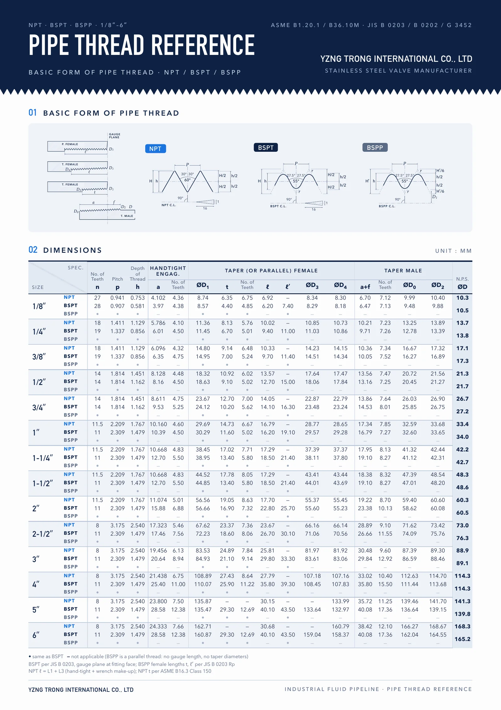
Table 1. Thread form and pipe outside diameter by size
| Size | NPT n | NPT p (mm) | NPT h (mm) | BSPT / BSPP n | BSPT / BSPP p (mm) | BSPT / BSPP h (mm) | Same pitch? | Pipe OD, NPS (in) | Pipe OD, NPS (mm) | Pipe OD, JIS G 3452 (mm) |
|---|---|---|---|---|---|---|---|---|---|---|
| 1/8″ | 27 | 0.941 | 0.753 | 28 | 0.907 | 0.581 | No | 0.405 | 10.3 | 10.5 |
| 1/4″ | 18 | 1.411 | 1.129 | 19 | 1.337 | 0.856 | No | 0.540 | 13.7 | 13.8 |
| 3/8″ | 18 | 1.411 | 1.129 | 19 | 1.337 | 0.856 | No | 0.675 | 17.1 | 17.3 |
| 1/2″ | 14 | 1.814 | 1.451 | 14 | 1.814 | 1.162 | Yes | 0.840 | 21.3 | 21.7 |
| 3/4″ | 14 | 1.814 | 1.451 | 14 | 1.814 | 1.162 | Yes | 1.050 | 26.7 | 27.2 |
| 1″ | 11.5 | 2.209 | 1.767 | 11 | 2.309 | 1.479 | No | 1.315 | 33.4 | 34.0 |
| 1-1/4″ | 11.5 | 2.209 | 1.767 | 11 | 2.309 | 1.479 | No | 1.660 | 42.2 | 42.7 |
| 1-1/2″ | 11.5 | 2.209 | 1.767 | 11 | 2.309 | 1.479 | No | 1.900 | 48.3 | 48.6 |
| 2″ | 11.5 | 2.209 | 1.767 | 11 | 2.309 | 1.479 | No | 2.375 | 60.3 | 60.5 |
| 2-1/2″ | 8 | 3.175 | 2.540 | 11 | 2.309 | 1.479 | No | 2.875 | 73.0 | 76.3 |
| 3″ | 8 | 3.175 | 2.540 | 11 | 2.309 | 1.479 | No | 3.500 | 88.9 | 89.1 |
| 4″ | 8 | 3.175 | 2.540 | 11 | 2.309 | 1.479 | No | 4.500 | 114.3 | 114.3 |
| 5″ | 8 | 3.175 | 2.540 | 11 | 2.309 | 1.479 | No | 5.563 | 141.3 | 139.8 |
| 6″ | 8 | 3.175 | 2.540 | 11 | 2.309 | 1.479 | No | 6.625 | 168.3 | 165.2 |
Look at the pitch columns before anything else. NPT and BSP threads (BSPT and BSPP have the same pitch at every size) coincide only at 1/2″ and 3/4″, where both families have 14 threads per inch. At 1/8″, 1/4″ and 3/8″ they differ by one thread per inch, from 1″ to 2″ by half a thread, and from 2-1/2″ up NPT drops to 8 threads per inch while BSP stays at 11. That pattern decides which mismatches screw together and which do not, and it comes up again below.
NPT, BSPT and BSPP: what each pipe thread is
NPT is the American taper pipe thread of ASME B1.20.1: a 60° thread angle, a taper of 1 in 16 on diameter, and a joint that seals on the thread itself. BSPT is the British Standard taper pipe thread, defined internationally in ISO 7-1 and in Japan in JIS B 0203: a 55° thread angle, the same 1 in 16 taper, also sealing on the thread. BSPP is the British Standard parallel pipe thread of ISO 228-1 and JIS B 0202: 55°, no taper, and a joint that must be sealed on a face by a washer, O-ring or bonded seal, because the thread cannot seal by itself.
The three are easiest to keep apart by their designations, because the designation is what appears on a drawing or an RFQ (request for quotation).
NPT is written as nominal size, threads per inch and the letters NPT, for example 1/2-14 NPT. The thread height is 0.8 times the pitch, and both the external and the internal thread are tapered. The ASME B1.20.1 standard defines it together with the straight pipe threads NPSC, NPSM and NPSL (for couplings, mechanical joints and locknuts) of the same family.
BSPT appears under several names that all mean the same thread. ISO 7-1 writes the external taper thread R and the internal taper thread Rc, and it also defines Rp, an internal parallel thread made to assemble with an R external thread. JIS B 0203 uses the same letters and keeps the older symbol PT in an appendix, so PT 1/2 on a Taiwanese or Japanese drawing is the same thread as R 1/2 or Rc 1/2. The thread height is 0.640327 times the pitch, and the crest and root are rounded.
BSPP is written G in ISO 228-1 and JIS B 0202, and PF in the older JIS notation. At each nominal size it has the same 55° form and the same pitch as BSPT, but no taper. The scope of ISO 228-1 states that the threads are for the mechanical assembly of fittings, valves and accessories, and that a pressure-tight joint is made by compressing two surfaces outside the thread with a seal between them. External G threads are made to tolerance class A or B.
Table 2. NPT, BSPT and BSPP side by side
| NPT | BSPT | BSPP | |
|---|---|---|---|
| Standard | ASME B1.20.1 | ISO 7-1; JIS B 0203 | ISO 228-1; JIS B 0202 |
| Designation | NPT (e.g. 1/2-14 NPT) | R external, Rc internal taper, Rp internal parallel; PT in older JIS | G (external class A or B); PF in older JIS |
| Thread angle | 60° | 55° | 55° |
| Taper | 1 in 16 on diameter | 1 in 16 on diameter | None (parallel) |
| Thread height | 0.8 p | 0.640327 p, rounded crest and root | 0.640327 p, rounded crest and root |
| Where the joint seals | On the thread, with sealant | On the thread, with sealant | On a face outside the thread: washer, O-ring or bonded seal |
| Mates with | NPT internal thread | Rc or Rp internal thread | G internal thread |
| Common in | United States, Canada | United Kingdom, Europe, Japan, Taiwan, much of Asia | Same regions as BSPT, where the joint has a sealing face |
How to read the detailed tables
Tables 3 to 6 give, for every nominal size, the engagement lengths on the external and internal thread (a, a + f, ℓ, ℓ′ and t) and the diameters at the points those lengths define (ØD0 to ØD4). The diameters are measured at or from the gauge plane, the reference cross-section where the basic diameters of a taper thread apply: at the hand-tight engagement L1 from the pipe end on NPT, and at the basic gauge length a on BSPT. Lengths are also given as a number of threads, because that is how a fitter counts turns. The diagram on the sheet above shows where each symbol sits on a male and a female thread.
The symbols follow the sheet. Where a value comes straight from a standard, the standard is named; where it is calculated from the standard’s basic dimensions, the formula is given, so any cell can be checked.
Column key
| Symbol | Meaning | NPT | BSPT |
|---|---|---|---|
| n | Threads per inch (threads in 25.4 mm) | ASME B1.20.1 | JIS B 0203 |
| p | Pitch, 25.4 ÷ n | Calculated | Calculated |
| h | Thread height | 0.8 p | 0.640327 p |
| a | Hand-tight engagement of the external thread, from the pipe end | L1 | Basic gauge length a, pipe end to gauge plane |
| a + f | Useful external thread length, from the pipe end | L2, effective thread length | a plus f, the minimum useful thread beyond the gauge plane |
| ℓ | Make-up length (NPT); useful internal taper thread length (BSPT) | L1 + L3; L3 is the wrench make-up allowance, 3 threads up to 2″ and 2 threads from 2-1/2″ | Minimum useful length of the internal taper thread (Rc), from the gauge plane |
| ℓ′ | Minimum useful length of a parallel internal thread (Rp), from the fitting face, allowing for incomplete threads | Not defined | JIS B 0203 |
| t | Minimum internal thread length with no incomplete threads | Class 150 fitting minimum thread length, ASME B16.3 | JIS B 0203 |
| ØD1 | Minor diameter at the gauge plane | E1 − h (E1 is the pitch diameter at the hand-tight plane) | d1 |
| ØD3 | Minor diameter at depth t into the internal thread | ØD1 − t ÷ 16 | ØD1 − t ÷ 16 |
| ØD4 | Minor diameter at depth ℓ into the internal thread | ØD1 − ℓ ÷ 16 | ØD1 − ℓ ÷ 16 |
| ØD0 | Major diameter at the pipe end (small end of the external thread) | E0 + h (E0 is the pitch diameter at the pipe end) | d − a ÷ 16 (d is the major diameter at the gauge plane) |
| ØD2 | Major diameter at the end of the useful external thread | ØD0 + L2 ÷ 16 | d + f ÷ 16 |
| OD | Outside diameter of the pipe the thread is cut on | NPS (Nominal Pipe Size) steel pipe, ASME B36.10M | SGP (carbon steel pipe for ordinary piping), JIS G 3452 |
Two notes on the internal thread columns. ASME B1.20.1 sets the thread dimensions and the make-up allowance L3, but not a minimum length of complete thread in a fitting, so the NPT t column uses the Class 150 minimum thread length of ASME B16.3 (Class 150 is one of the two pressure classes of threaded fittings in that standard), as listed by a fitting maker and a stainless fitting distributor. No second source was found for 5″ and 6″, so those two cells are blank. ISO 228-1 and JIS B 0202 set no thread length for G; the ℓ′ and t values in Table 5 are for Rp, and the sheet above uses them as the female lengths for a parallel thread.
NPT and BSPT thread dimensions, 1/8″ to 6″
Tables 3 and 4 are NPT, Tables 5 and 6 are BSPT, and Table 7 is BSPP. Everything is in millimeters except the columns marked (in), and threads per inch is the count over 25.4 mm. The inch values in Table 3 are the ASME B1.20.1 basic dimensions; the millimeter columns convert them at 25.4 mm per inch.
Table 3. NPT engagement lengths, ASME B1.20.1
| Size | n | a = L1 (mm) | L1 (in) | a in threads | a + f = L2 (mm) | L2 (in) | ℓ = L1 + L3 (mm) | t, B16.3 min. (mm) | t in threads |
|---|---|---|---|---|---|---|---|---|---|
| 1/8″ | 27 | 4.102 | 0.1615 | 4.36 | 6.70 | 0.2639 | 6.92 | 6.35 | 6.75 |
| 1/4″ | 18 | 5.786 | 0.2278 | 4.10 | 10.21 | 0.4018 | 10.02 | 8.13 | 5.76 |
| 3/8″ | 18 | 6.096 | 0.240 | 4.32 | 10.36 | 0.4078 | 10.33 | 9.14 | 6.48 |
| 1/2″ | 14 | 8.128 | 0.320 | 4.48 | 13.56 | 0.5337 | 13.57 | 10.92 | 6.02 |
| 3/4″ | 14 | 8.611 | 0.339 | 4.75 | 13.86 | 0.5457 | 14.05 | 12.70 | 7.00 |
| 1″ | 11.5 | 10.160 | 0.400 | 4.60 | 17.34 | 0.6828 | 16.79 | 14.73 | 6.67 |
| 1-1/4″ | 11.5 | 10.668 | 0.420 | 4.83 | 17.95 | 0.7068 | 17.29 | 17.02 | 7.71 |
| 1-1/2″ | 11.5 | 10.668 | 0.420 | 4.83 | 18.38 | 0.7235 | 17.29 | 17.78 | 8.05 |
| 2″ | 11.5 | 11.074 | 0.436 | 5.01 | 19.22 | 0.7565 | 17.70 | 19.05 | 8.63 |
| 2-1/2″ | 8 | 17.323 | 0.682 | 5.46 | 28.89 | 1.1375 | 23.67 | 23.37 | 7.36 |
| 3″ | 8 | 19.456 | 0.766 | 6.13 | 30.48 | 1.2000 | 25.81 | 24.89 | 7.84 |
| 4″ | 8 | 21.438 | 0.844 | 6.75 | 33.02 | 1.3000 | 27.79 | 27.43 | 8.64 |
| 5″ | 8 | 23.800 | 0.937 | 7.50 | 35.72 | 1.4063 | 30.15 | — | — |
| 6″ | 8 | 24.333 | 0.958 | 7.66 | 38.42 | 1.5125 | 30.68 | — | — |
Table 4. NPT thread diameters (mm)
| Size | Pipe OD | ØD0 (pipe end) | ØD2 (end of a + f) | ØD1 (gauge plane) | ØD3 (at t) | ØD4 (at ℓ) |
|---|---|---|---|---|---|---|
| 1/8″ | 10.3 | 9.99 | 10.40 | 8.74 | 8.34 | 8.30 |
| 1/4″ | 13.7 | 13.25 | 13.89 | 11.36 | 10.85 | 10.73 |
| 3/8″ | 17.1 | 16.67 | 17.32 | 14.80 | 14.23 | 14.15 |
| 1/2″ | 21.3 | 20.72 | 21.56 | 18.32 | 17.64 | 17.47 |
| 3/4″ | 26.7 | 26.03 | 26.90 | 23.67 | 22.87 | 22.79 |
| 1″ | 33.4 | 32.59 | 33.68 | 29.69 | 28.77 | 28.65 |
| 1-1/4″ | 42.2 | 41.32 | 42.44 | 38.45 | 37.39 | 37.37 |
| 1-1/2″ | 48.3 | 47.39 | 48.54 | 44.52 | 43.41 | 43.44 |
| 2″ | 60.3 | 59.40 | 60.60 | 56.56 | 55.37 | 55.45 |
| 2-1/2″ | 73.0 | 71.62 | 73.42 | 67.62 | 66.16 | 66.14 |
| 3″ | 88.9 | 87.39 | 89.30 | 83.53 | 81.97 | 81.92 |
| 4″ | 114.3 | 112.63 | 114.70 | 108.89 | 107.18 | 107.16 |
| 5″ | 141.3 | 139.46 | 141.70 | 135.87 | — | 133.99 |
| 6″ | 168.3 | 166.27 | 168.67 | 162.71 | — | 160.79 |
Table 5. BSPT (R, Rc, PT) engagement lengths, JIS B 0203 (mm)
| Size | n | a (gauge length) | a in threads | a + f | ℓ (Rc, min.) | ℓ′ (Rp, min.) | t (min.) | t in threads |
|---|---|---|---|---|---|---|---|---|
| 1/8″ | 28 | 3.97 | 4.38 | 6.47 | 6.20 | 7.40 | 4.40 | 4.85 |
| 1/4″ | 19 | 6.01 | 4.50 | 9.71 | 9.40 | 11.00 | 6.70 | 5.01 |
| 3/8″ | 19 | 6.35 | 4.75 | 10.05 | 9.70 | 11.40 | 7.00 | 5.24 |
| 1/2″ | 14 | 8.16 | 4.50 | 13.16 | 12.70 | 15.00 | 9.10 | 5.02 |
| 3/4″ | 14 | 9.53 | 5.25 | 14.53 | 14.10 | 16.30 | 10.20 | 5.62 |
| 1″ | 11 | 10.39 | 4.50 | 16.79 | 16.20 | 19.10 | 11.60 | 5.02 |
| 1-1/4″ | 11 | 12.70 | 5.50 | 19.10 | 18.50 | 21.40 | 13.40 | 5.80 |
| 1-1/2″ | 11 | 12.70 | 5.50 | 19.10 | 18.50 | 21.40 | 13.40 | 5.80 |
| 2″ | 11 | 15.88 | 6.88 | 23.38 | 22.80 | 25.70 | 16.90 | 7.32 |
| 2-1/2″ | 11 | 17.46 | 7.56 | 26.66 | 26.70 | 30.10 | 18.60 | 8.06 |
| 3″ | 11 | 20.64 | 8.94 | 29.84 | 29.80 | 33.30 | 21.10 | 9.14 |
| 4″ | 11 | 25.40 | 11.00 | 35.80 | 35.80 | 39.30 | 25.90 | 11.22 |
| 5″ | 11 | 28.58 | 12.38 | 40.08 | 40.10 | 43.50 | 29.30 | 12.69 |
| 6″ | 11 | 28.58 | 12.38 | 40.08 | 40.10 | 43.50 | 29.30 | 12.69 |
Table 6. BSPT thread diameters (mm)
| Size | Pipe OD | ØD0 (pipe end) | ØD2 (end of a + f) | ØD1 (gauge plane) | ØD3 (at t) | ØD4 (at ℓ) |
|---|---|---|---|---|---|---|
| 1/8″ | 10.5 | 9.48 | 9.88 | 8.57 | 8.29 | 8.18 |
| 1/4″ | 13.8 | 12.78 | 13.39 | 11.45 | 11.03 | 10.86 |
| 3/8″ | 17.3 | 16.27 | 16.89 | 14.95 | 14.51 | 14.34 |
| 1/2″ | 21.7 | 20.45 | 21.27 | 18.63 | 18.06 | 17.84 |
| 3/4″ | 27.2 | 25.85 | 26.75 | 24.12 | 23.48 | 23.24 |
| 1″ | 34.0 | 32.60 | 33.65 | 30.29 | 29.57 | 29.28 |
| 1-1/4″ | 42.7 | 41.12 | 42.31 | 38.95 | 38.11 | 37.80 |
| 1-1/2″ | 48.6 | 47.01 | 48.20 | 44.85 | 44.01 | 43.69 |
| 2″ | 60.5 | 58.62 | 60.08 | 56.66 | 55.60 | 55.23 |
| 2-1/2″ | 76.3 | 74.09 | 75.76 | 72.23 | 71.06 | 70.56 |
| 3″ | 89.1 | 86.59 | 88.46 | 84.93 | 83.61 | 83.06 |
| 4″ | 114.3 | 111.44 | 113.68 | 110.07 | 108.45 | 107.83 |
| 5″ | 139.8 | 136.64 | 139.15 | 135.47 | 133.64 | 132.97 |
| 6″ | 165.2 | 162.04 | 164.55 | 160.87 | 159.04 | 158.37 |
Table 7. BSPP (G, PF) basic diameters, JIS B 0202 and ISO 228-1 (mm)
BSPP shares n, p and h with BSPT at every size, and the same major, pitch and minor diameters as BSPT at its gauge plane. Because the thread is parallel there is no gauge length and no taper diameter: the basic diameters apply along the whole thread.
| Size | n | p | h | Major diameter d | Pitch diameter d2 | Minor diameter d1 |
|---|---|---|---|---|---|---|
| 1/8″ | 28 | 0.907 | 0.581 | 9.728 | 9.147 | 8.566 |
| 1/4″ | 19 | 1.337 | 0.856 | 13.157 | 12.301 | 11.445 |
| 3/8″ | 19 | 1.337 | 0.856 | 16.662 | 15.806 | 14.950 |
| 1/2″ | 14 | 1.814 | 1.162 | 20.955 | 19.793 | 18.631 |
| 3/4″ | 14 | 1.814 | 1.162 | 26.441 | 25.279 | 24.117 |
| 1″ | 11 | 2.309 | 1.479 | 33.249 | 31.770 | 30.291 |
| 1-1/4″ | 11 | 2.309 | 1.479 | 41.910 | 40.431 | 38.952 |
| 1-1/2″ | 11 | 2.309 | 1.479 | 47.803 | 46.324 | 44.845 |
| 2″ | 11 | 2.309 | 1.479 | 59.614 | 58.135 | 56.656 |
| 2-1/2″ | 11 | 2.309 | 1.479 | 75.184 | 73.705 | 72.226 |
| 3″ | 11 | 2.309 | 1.479 | 87.884 | 86.405 | 84.926 |
| 4″ | 11 | 2.309 | 1.479 | 113.030 | 111.551 | 110.072 |
| 5″ | 11 | 2.309 | 1.479 | 138.430 | 136.951 | 135.472 |
| 6″ | 11 | 2.309 | 1.479 | 163.830 | 162.351 | 160.872 |
NPT vs BSPT vs BSPP: which threads fit together
NPT and BSPT do not seal against each other at any size, even at 1/2″ and 3/4″ where they screw together. BSPP does not seal against either taper thread, because it does not seal on the thread at all. The one parallel female thread meant to seal with a BSPT male is Rp, which belongs to ISO 7-1 and JIS B 0203, not to the G thread of BSPP.
Two things keep NPT and BSPT apart. The first is the pitch pattern in Table 1: at most sizes the threads per inch differ, so the parts bind within a few turns. The second is the thread angle, 60° against 55°, and it is the one that causes trouble, because at 1/2″ and 3/4″ the pitches match and the parts run together by hand. With a 5° difference in thread angle (2.5° on each flank), the flanks do not lie on each other, so a helical gap runs the length of the engagement. Sealant may hide the gap at first; it does not remove it.
Parallel against taper fails for a different reason. A G or PF external thread in an Rc female contacts only over the last turn at the leading end of the male, where the diameters meet, with clearance along the rest of the engagement. An R or PT external thread in a G female is closer to workable, since the pitch and angle match, but the G thread of ISO 228-1 has its own tolerances and, by that standard’s own scope, is not meant to make a pressure-tight joint on the thread. If a parallel female thread has to seal with a taper male, specify Rp, not G.
How to identify a pipe thread on a valve or fitting
Three measurements settle it. The outside diameter of the male thread gives the nominal size; the number of threads per inch separates NPT from BSP at every size except 1/2″ and 3/4″; and the thread angle, or the presence of a taper, separates the rest. Compare each reading with the chart.
Start with the outside diameter, measured with calipers at the first full thread near the pipe end (the ØD0 column), or on the pipe itself (the OD column). The nominal size is not the diameter: a 1/2″ pipe thread measures about 21 mm, a 1″ thread about 33 mm. From 1/8″ to 2″, and at 3″, the NPT and BSPT ØD0 values at the same nominal size are within a millimeter of each other, so this step identifies the size, not the standard. At 2-1/2″, 4″, 5″ and 6″ the ØD0 values differ by 1.2 to 4.2 mm, so compare the reading with both columns.
Next, count the threads per inch with a pitch gauge, or count the thread crests over 25.4 mm. Read the result against Table 1. A count of 27, 18, 11.5 or 8 is NPT; 28, 19 or 11 is BSP. A count of 14 is either, at 1/2″ or 3/4″, and needs the third check.
For the third check, a 55° and 60° thread angle gauge is the direct way; held against the thread in good light, the wrong angle shows a gap at the flank. If no gauge is at hand, the taper gives a second clue, though it does not separate NPT from BSPT: a taper thread changes about 1 mm in diameter for every 16 mm of length, so calipers at the first and last full thread read differently, while a parallel thread reads the same. A taper male thread also stops after a few turns when run by hand into its matching female, four to seven turns on sizes up to 2″ (the basic values in the a column, in threads), while a parallel thread runs in to the end. Then check the marking: R, Rc, PT or BSPT on a drawing means the 55° taper thread; G, PF or BSPP means the 55° parallel thread; NPT means NPT.
For tube fittings, port threads and the less common straight threads, the Swagelok thread and end connection identification guide (PDF) goes through the same procedure step by step, with reference tables for each type.
Which pipe thread to specify on a stainless steel valve or fitting
Specify the thread by its standard and designation on the RFQ: 1/2 NPT, Rc 1/2 (PT 1/2) or G 1/2 (PF 1/2), and say which end of a valve is male and which is female. We are Yzng Trong, a stainless steel ball valve manufacturer in Taichung, Taiwan, making valves since 1999. Our threaded ball valves are made in PT (the JIS name for BSPT), NPT or PF (the JIS name for BSPP), to the thread stated on the order; the threaded pipe fittings on this site are PT. The thread is cut when the valve is made and cannot be changed afterwards, so the RFQ is the moment to settle it.
Four situations cover most orders. A plant in the United States or Canada runs on NPT, so ask for NPT and write it on the order; the valve will then mate with any NPT fitting in the plant. A plant in Taiwan or Japan runs on PT, and much of Asia on the same thread under its ISO names R and Rc; a PT valve mates with the Rc and Rp fittings already installed, and it is the thread to ask for when replacing a valve that came from Taiwan or Japan. A plant that seals on a face with bonded washers or O-rings uses PF, and the mating part must be the parallel thread too.
The fourth situation is the one the identification section above exists for: a female fitting is already installed and nobody is sure what it is. Measure it before ordering. A valve in the wrong thread cannot be reworked into the right one, and an adapter adds a joint, which is one more place for a leak. Our guide to valve end connections covers when a threaded end is the right choice at all, against socket weld and butt weld ends; threaded ends are the usual choice on small-bore lines. The threaded ball valves listed below are rated 1000 WOG, a cold working pressure that our WOG rating guide explains.
The threaded models on this site are the seal-welded two-piece ball valve (V-2B) in 1/4″ to 3″, with a 4″ version that uses a bolted end cap, the one-piece ball valve (R-1B) in 1/4″ to 3″, the three-piece ball valve with threaded or socket weld ends in 1/4″ to 4″, and a male-by-female ball valve for the cases where the valve itself replaces a nipple. Threaded stainless steel pipe fittings, such as the PT pipe coupling, are listed in their own category. The valve RFQ guide lists the other items an inquiry should carry, from quantity to delivery date and destination.
Common pipe thread mistakes
The mistakes below are the ones that produce leaking joints or valves that cannot be installed. Most of them come from treating NPT and BSP as one family, or a nominal size as a measurement.
- Mixing NPT and BSPT at 1/2″ or 3/4″. Both have 14 threads per inch at these two sizes, so a mismatched pair screws together by hand and the 5° difference in thread angle is invisible. The joint leaks along the flanks under pressure. Check the angle, or the marking, before assembly.
- Expecting a BSPP (G, PF) thread to seal on the thread. It cannot; ISO 228-1 says so in its scope. A G joint needs a washer, O-ring or bonded seal on the face, and the mating part must be parallel too.
- Writing “BSP” without T or P. BSP alone does not say whether the thread is taper or parallel, and the two are not interchangeable. Write BSPT or BSPP, or better, R, Rc, Rp or G with the size.
- Reading the nominal size as the outside diameter. A 1/2″ thread is about 21 mm across, not 12.7 mm. Use the OD and ØD0 columns to match a measurement to a size.
- Treating the pipe outside diameter as one number. NPS pipe to ASME B36.10M and JIS G 3452 pipe differ at the same nominal size, by 0.4 mm at 1/2″ and by over 3 mm at 2-1/2″ and 6″, which matters when a thread is cut on site.
- Wrenching past the make-up length. ASME B1.20.1 provides internal thread length for about three turns of wrench make-up beyond hand-tight on sizes up to 2″, and two turns from 2-1/2″ up; the NPT ℓ column is that total. A joint that still leaks at that depth should be taken apart and remade with fresh sealant, or the part replaced; more torque will not close the leak.
How this chart was calculated
Every value in Tables 1 and 3 to 7 is either taken from a standard’s table or calculated from a standard’s basic dimensions with the formulas in the column key, in exact arithmetic and rounded once at the end. Blank cells are values we could not confirm from two sources.
The NPT values start from the pitch diameters at the pipe end and at the hand-tight plane (E0 and E1), the lengths L1, L2 and L3, and h = 0.8p, as published for ASME B1.20.1. The BSPT values take d, d1, a, f, ℓ, ℓ′ and t directly from the JIS B 0203:1999 tables; where JIS and ISO 7-1 round the gauge length a differently (3.97 against 4 mm at 1/8″, for example) the JIS value is used throughout. BSPP basic diameters are from JIS B 0202:1999, which are the ISO 228-1 values. Pipe outside diameters are NPS per ASME B36.10M for NPT and SGP (carbon steel pipe for ordinary piping) per JIS G 3452 for BSPT. The one column no thread standard defines, the minimum internal thread length t for NPT, uses the ASME B16.3 Class 150 figures, and its 5″ and 6″ cells stayed blank because only one source could be found for them.
The finished sheet was checked cell by cell against the calculation file, and the calculation was checked by a second pass from different sources.
Frequently asked questions
Are NPT and BSPT threads interchangeable?
No. NPT has a 60° thread angle and BSPT 55°, so the flanks never match, even at 1/2″ and 3/4″ where both have 14 threads per inch and the parts screw together. At every other size the pitch differs too, from 27 against 28 threads per inch at 1/8″ to 8 against 11 from 2-1/2″ up. A mixed joint has a helical gap along the whole engagement, which sealant may hide at first but does not remove. Order the valve or fitting in the thread of the mating part, or use an adapter with the correct thread on each end.
Is PT the same as BSPT, and PF the same as BSPP?
Yes. PT is the older JIS B 0203 symbol for the 55° taper pipe thread that ISO 7-1 writes R (external) and Rc (internal), the thread known elsewhere as BSPT. PF is the older JIS B 0202 symbol for the 55° parallel thread that ISO 228-1 writes G, known as BSPP. The dimensions are identical; only the letters differ. In Taiwan and Japan the old symbols are still common on drawings, which is why our product pages say PT and PF. In the BSP family, Rp, the parallel internal thread of ISO 7-1 and JIS B 0203, is the parallel thread made to seal with a taper male; G is not.
What is the actual diameter of a 1/2″ pipe thread?
About 21 mm, not 12.7 mm. Nominal pipe sizes are inherited from early pipe bores and no longer match any dimension of the thread. From the chart, a 1/2″ NPT male thread measures 20.72 mm at the pipe end and 21.56 mm at the end of the useful thread, on pipe with a 21.3 mm outside diameter. A 1/2″ BSPT male thread measures 20.45 mm and 21.27 mm, on JIS pipe of 21.7 mm. The two are too close to tell apart with calipers; the outside diameter identifies the nominal size, and the thread count or the thread angle identifies the standard.
How many turns should a taper pipe thread engage?
Use the a and ℓ columns. Hand-tight engagement (a) is between 4 and 5.5 turns on sizes up to 1-1/2″ for both NPT and BSPT. ASME B1.20.1 then provides internal thread length for a further 3 turns of wrench make-up (L3) on sizes up to 2″ and 2 turns from 2-1/2″ up, and the NPT ℓ column is that total: 13.57 mm on 1/2″, about 7.5 threads. For BSPT the ℓ column is the minimum useful length of the female taper thread in the fitting, 12.70 mm on 1/2″. If the joint still leaks at that depth, remake it with fresh sealant or replace the part.
Which pipe thread do stainless steel ball valves from Taiwan use?
Whichever thread is stated on the order. Drawings in Taiwan and Japan usually carry the JIS symbol PT for the 55° taper thread (BSPT), and a PT male thread is designed to seal in an Rc or Rp female, but ask any supplier which thread they cut rather than assume it. Our threaded ball valves are made in PT, in NPT for North American piping, or in PF (BSPP) for lines that seal on a face. Write the thread standard on the RFQ with the size and quantity, and on a male-by-female valve say which end is which; the thread cannot be changed after the valve is made.
Summary
Use Table 1 to identify a thread by pitch and outside diameter, Tables 3 to 6 for the engagement lengths and diameters when you design or inspect a joint, and the designations NPT, R, Rc, Rp, G, PT and PF when you write the RFQ. NPT is 60° and tapered, BSPT is 55° and tapered, BSPP is 55° and parallel, and none of the three seals against another. If you need stainless steel ball valves in a specific thread, or PT fittings, send the standard, the size and the quantity through our request a quote page; we reply within 24 hours.