
A manual, a pneumatic and an electric ball valve can share the same body, the same seats and the same fluid conditions. The difference is not inside the valve. It is in who or what rotates the ball, how often it happens, and what the system should do when air or power is lost.
Selection goes wrong when it starts from the question “which type is more advanced.” It goes right when it starts from the operating situation on site: how often the valve operates, whether an operator can reach it, what utilities already exist, and whether a control system needs to command the valve or know its position.
A Quick Comparison for First Selection
The table below is a starting point, not a final answer. Two plants with the same valve duty can reasonably land on different choices because their utilities and staffing differ.
| Operation type | Best starting point | What the site must have | What to confirm before ordering |
|---|---|---|---|
| Manual | Infrequent operation, an operator can reach the valve, no remote control or feedback needed | An operator who can get to the valve safely | Handle clearance and access; whether the operating frequency may grow later |
| Pneumatic | Frequent or remote on/off switching in a plant that already runs suitable compressed air | Clean, dry compressed air with enough capacity at the actuator | Required fail position; solenoid and control interface; actuator sizing for the actual service |
| Electric | Remote operation where there is no air supply but suitable electrical power is available | A power supply matching the actuator specification, plus wiring to the control point | Supply voltage and duty; on/off or modulating; what the actuator does on loss of power |
None of these rows is a fixed rule. A rarely operated valve in an unreachable pit may still justify automation. A frequently operated valve next to a control station may stay manual because the operator is already standing there.
Looking for the valve itself?
Manual Ball Valves — browse the full range
Pneumatic Ball Valves — double acting or spring return
Electric Valve Actuator with Battery Backup — AC 110V/220V/380V or DC 24V/48V
When a Manual Ball Valve Makes Sense
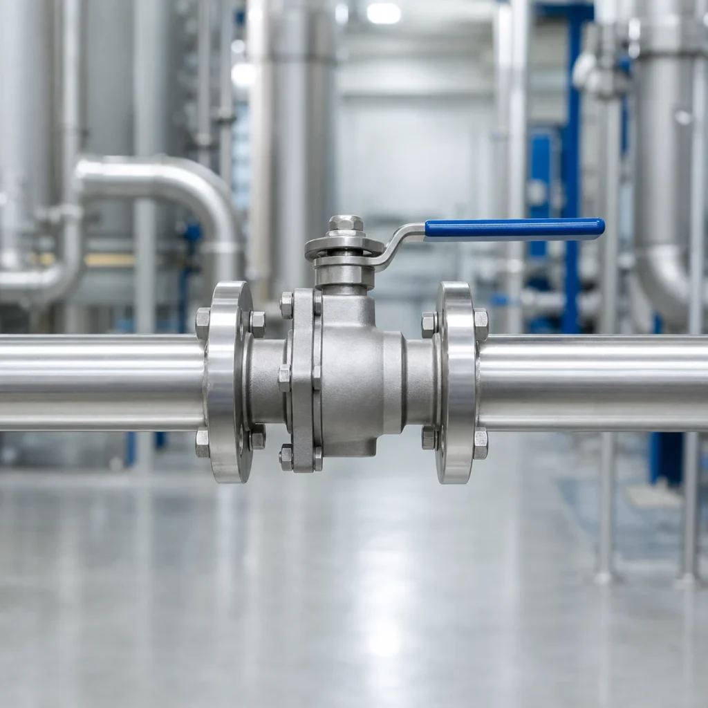
A manual ball valve fits valves that are operated occasionally, by a person who can reach them, with no need for remote command or position feedback. Typical places include isolation points at equipment, maintenance bypass lines, drain and vent connections, and seasonal changeover valves that move a few times a year. The quarter-turn handle shows the valve position at a glance, and there is no actuator, tubing or wiring to maintain. A manual flanged ball valve on an isolation point is a common example of this role.
Manual operation stops making sense in a few specific situations. If the valve sits on a pipe rack, in a pit or on top of a tank, “an operator can reach it” can mean a ladder and a permit. If the valve operates many times a day, sending a person each time adds delay. If the valve must act together with other equipment, or the control room needs to know whether it is open, a bare handle cannot provide that. Larger valves and higher differential pressure also raise the handle effort; when operators start struggling with the handle, the valve may be a candidate for automation.
When Pneumatic Operation Makes Sense
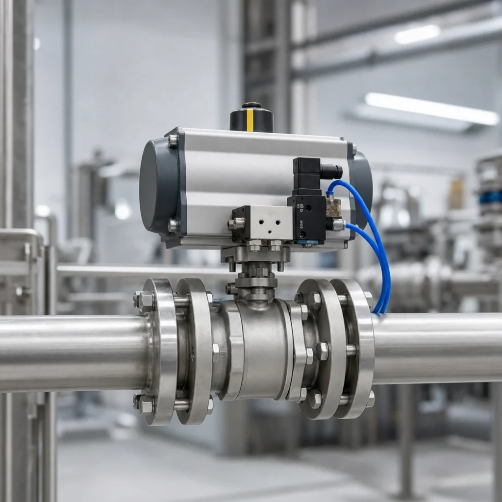
Pneumatic operation makes sense when the plant already runs compressed air and the valve needs to switch more often, or from further away, than an operator can reasonably manage. A solenoid valve turns the actuator into a remote on/off device, and frequent cycling stops depending on someone walking to the valve. A pneumatic flanged ball valve is a typical form this takes on flanged process lines.
The gating question is the air itself. If suitable compressed air already reaches the valve location, pneumatic operation is usually the natural first candidate. If there is no air system, installing one just to automate a single valve changes the whole comparison, and electric operation deserves a serious look.
A double acting actuator uses air for both opening and closing and has no built-in spring, so on loss of air it does not move to a predetermined fail position. A spring return actuator can provide a predetermined fail position, but the actual behavior still has to be confirmed for the assembled valve and actuator under the real operating conditions. How to define the fail position, size the torque and check the mounting is covered in the valve actuator selection guide.
When Electric Operation Makes Sense
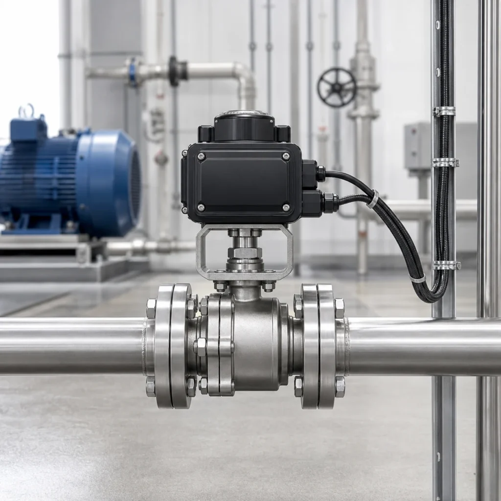
Electric operation makes sense where there is no practical air supply, suitable electrical power is available, and the valve needs remote command. Cable replaces air tubing, which often favors single valve locations far from any air line: a remote pump station, a rooftop line or an outbuilding. Wiring, supply voltage and the control interface then become the items to plan, so state early whether the control system needs only an open/close command or also position feedback.
A standard electric ball valve is normally an on/off device. If the process needs to regulate flow, specify a model with a positioner or modulating capability instead of assuming the standard unit can do it. What an electric actuator does on loss of power depends on the model. Do not assume a fail-open or fail-closed action; confirm it for the specific model before ordering.
Questions That Decide the Choice
- How often does the valve operate?
- Can an operator reach it quickly?
- Is clean compressed air available?
- Is suitable electrical power available?
- Is remote command or position feedback needed?
- What should happen on loss of air or power?
- Is the valve only on/off, or does the process actually need modulation?
- What are the fluid, pressure, temperature and end connection?
If some answers are unknown, settle them before comparing quotations. They decide which quotation is relevant.
Do Not Choose the Actuator Before Confirming the Valve
Operation type is only half the decision. The actuator still has to match the specific valve and duty: the torque required under actual service conditions, the mounting interface, the rotation angle, and the stem coupling all need to be confirmed rather than assumed from a catalogue page. An actuator that fits the drawing can still be wrong for the service. These checks are worked through in the valve actuator selection guide.
Frequently Asked Questions
Is a pneumatic ball valve always better than a manual ball valve?
No. For a valve that operates a few times a year, with an operator nearby and no remote control requirement, a manual ball valve is often the reasonable choice. Pneumatic operation earns its place when switching is frequent, the valve is hard to reach, or a control system has to command it. The deciding factors are operating frequency, access and control needs.
When is an electric ball valve the better option?
Electric operation is usually the better fit when the site has no practical compressed air supply but suitable electrical power, and the valve needs to be operated remotely. Before ordering, confirm the supply voltage, whether the duty is on/off or modulating, and what the actuator does on loss of power.
Does a double-acting pneumatic actuator fail to a safe position?
No, not by itself. A double acting actuator uses air pressure for both opening and closing and has no built-in spring, so on loss of air it does not drive the valve to a predetermined position. If the process requires a defined fail position, a spring return actuator is a usual starting point, and the actual fail behavior must still be confirmed for the assembled valve and actuator under the real operating conditions.
Can a standard electric ball valve control flow precisely?
A standard electric ball valve is an on/off device: it opens and closes on command, which is not the same as precise flow control. If the process needs to modulate flow, specify an actuator with a positioner or modulating capability, and confirm that the valve and actuator combination suits the control task.
What information should I send before requesting an automated ball valve?
Send the fluid, working pressure and temperature, valve size and end connection, and how often the valve will operate. Add what utilities exist on site: the air pressure available for a pneumatic actuator, or the supply voltage for an electric one. State the required position on loss of air or power, and whether the control system needs remote command or position feedback. With these points, a supplier can propose a matched valve and actuator instead of a generic one.