
Choosing a 3-way ball valve by its port name alone is a common source of piping mistakes. Two valves can both be sold as “L-port,” yet connect their ports differently at each handle position. Before you compare prices or materials, get two documents for the exact model you are considering: the port diagram and the handle-position flow chart. Together they show which of the three ports, call them A, B and C, are connected in every position the valve can reach. This guide explains how to read L-port and T-port flow paths, where each pattern fits, and which details to confirm before you specify the valve.
Start with the Flow Path, Not the Port Name
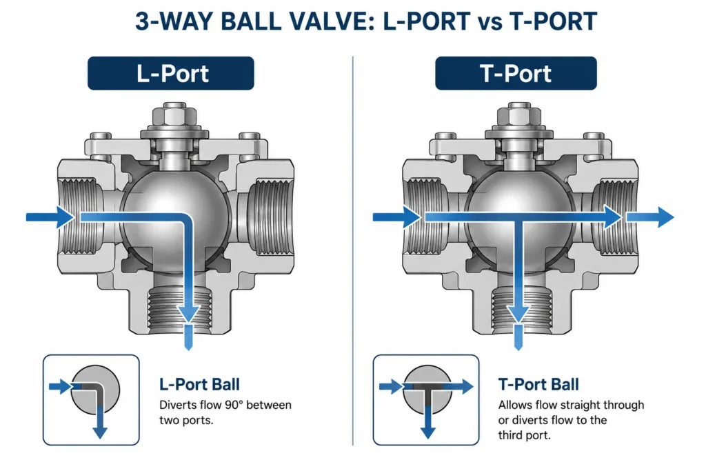
The names L-port and T-port describe the shape of the hole drilled through the ball, not a guaranteed behavior. Manufacturers differ in how they label the ports, where the common port sits, which direction the handle points relative to the flow path, and whether the valve rotates 90 degrees, 180 degrees, or has intermediate stops. The same handle angle can mean different connections on two different valves.
A practical way to specify the valve is to name the three ports A, B and C, then write down which pairs must be connected in each position your process needs. The table below shows one common L-port arrangement as an illustration of the method, not as a promise about any particular valve.
| Handle position | A to B | A to C | B to C |
|---|---|---|---|
| Position 1 | Öffnen | Geschlossen | Geschlossen |
| Position 2 (90° turn) | Geschlossen | Öffnen | Geschlossen |
Example flow concept only. Confirm the exact port and handle-position diagram for the selected model.
Writing your requirement in this A/B/C format has a second benefit: it lets a supplier check it against a specific model instead of guessing what you mean by “diverting” or “switching.”
L-Port: Usually Used for Selecting One Path
An L-port ball has a 90-degree bore. In most arrangements it connects a common port to one of two branch ports, so the valve acts as a selector: flow from A goes to B in one position and to C in another. This makes L-port valves the usual choice for tasks such as feeding a line from one of two tanks, or sending a pump discharge to one of two destinations.
What an L-port name does not tell you is how tightly the unused branch is closed off, or what happens during the transition between positions. Sealing performance depends on the seat design, seat material, pressure, temperature and the condition of the valve, and every soft-seated ball valve has an allowable leakage class rather than an absolute guarantee. If the branch you are not using must stay genuinely isolated, treat that as a separate requirement to verify, not something the letter L provides. Our manuelles 3-Wege-Kugelventil product page shows a typical stainless steel L-port and T-port configuration you can check against your flow requirement.
Before selecting an L-port model, confirm:
- Which port is the common port on that specific model.
- The actual connections at each position for a 90-degree or 180-degree operation, including any position where all paths are closed, if the model offers one.
- Whether the unused branch needs true shutoff or isolation, and what leakage rate is acceptable there.
- Seat material, working pressure and temperature, and the allowable internal leakage for your service.
If a small internal leak on the closed branch would cause a real problem, say so in your inquiry. It changes which valve, seat and test requirements are appropriate. For background on how seats leak and wear, see our guide to diagnosing a leaking ball valve.
T-Port: Routing, Combining or Bypass Duties
A T-port ball has a bore shaped like the letter T, which allows connection patterns an L-port cannot make. Depending on the bore orientation and the positions the valve can reach, a T-port can route a common flow to either branch, connect all three ports at once, or combine two incoming streams into one outgoing line. That flexibility suits duties such as bypass loops around equipment, simple flow routing between lines, and joining two supplies into one header.
Two cautions apply when selecting a T-port. First, the available positions differ between models: some T-port valves cannot fully close any path, while others have a position that shuts off one branch. Only the handle-position chart for the specific model tells you which patterns you actually get. Second, “two ports connected at the same time” is not the same as controlled mixing. When two streams meet inside a T-port valve, the resulting ratio is set by the pressures and resistances of the two lines, not by the valve. If your process needs a fixed blend ratio or continuous adjustment, that calls for a control solution designed for modulation, not an assumption that a standard 3-way ball valve will regulate the blend.
When a Standard 3-Way Ball Valve Is Not the Right Valve
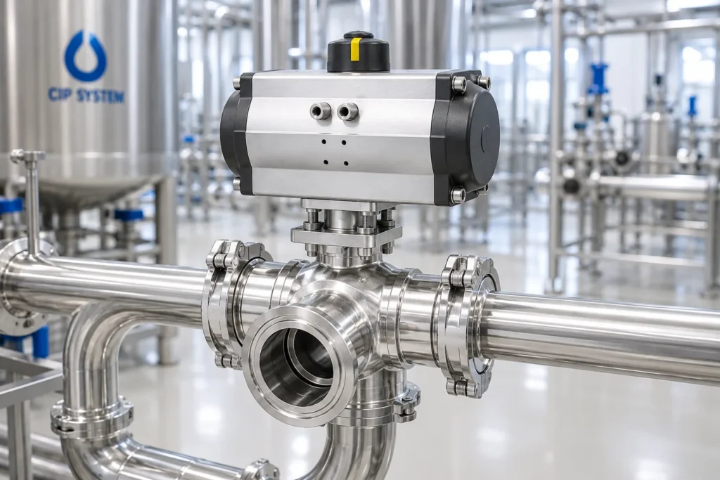
A standard 3-way ball valve is a compact way to select, route or combine flow. It is not the answer to every three-port problem. Treat the following situations as separate engineering questions that need review against the actual model and system, because port choice alone cannot solve them:
- Preventing cross-contamination between two products. A single ball with seats is one layer of sealing. Where mixing two media is unacceptable, systems normally use dedicated arrangements such as double isolation with a monitored space between the products. A general-purpose 3-way ball valve is not a mixproof valve.
- Double isolation or mixproof function. If your specification names these functions, the valve arrangement must be designed and verified for them, not approximated with a single L-port.
- Precise blend ratios. As described above, this needs a modulating control scheme.
- A defined failure position. The valve and actuator combination must be chosen for the required fail behavior; see the actuation section below.
- High-purity, hygienic, steam or vacuum service. Each of these puts specific demands on seat materials, surface finish, sealing direction or leakage rate. They are served by models designed for that duty, such as our sanitary 3-way ball valve und 3-way vacuum ball valve, and the suitability of any model still has to be confirmed against your operating conditions.
Manual, Pneumatic or Electric Operation
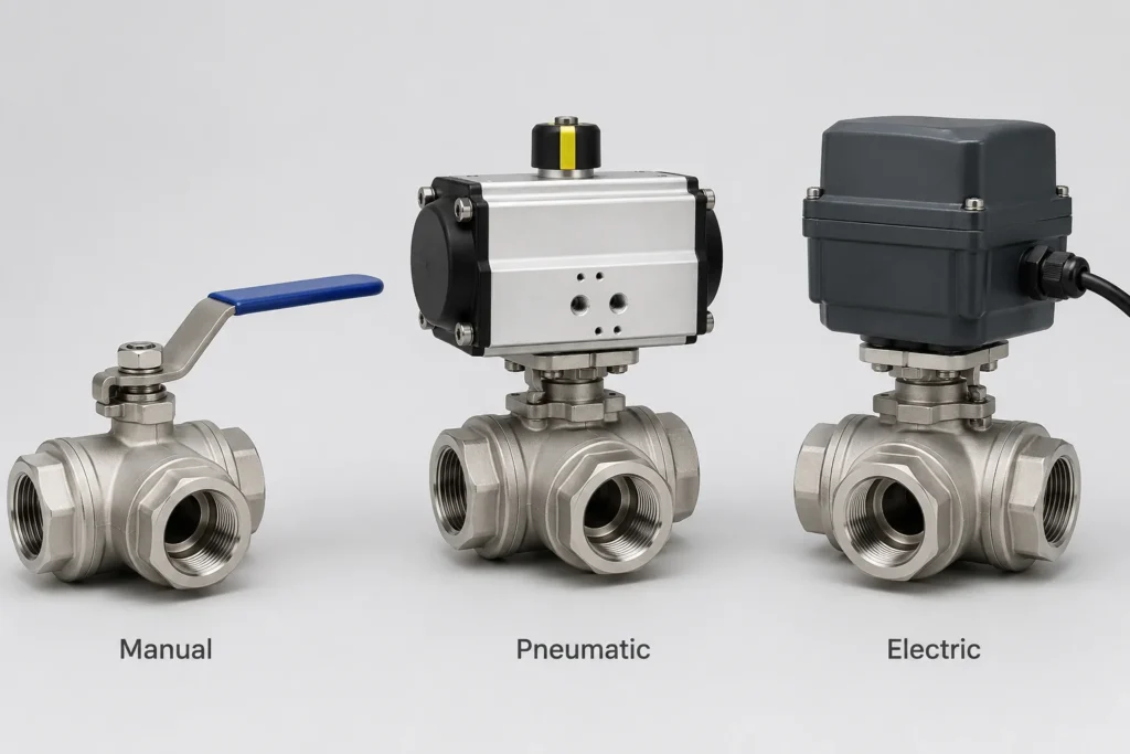
The right operation method follows from who or what needs to move the valve, how often, and what should happen when power or air is lost.
| Betrieb | Typical use | Key point to confirm |
|---|---|---|
| Manual handle | Positions changed a few times a day or less, with someone available at the valve | Handle direction and stops match the flow chart you specified |
| Pneumatic, double-acting (DA) | Remote on/off switching where compressed air is available | No spring inside: on loss of air it does not drive itself to a safe position, so define a failure strategy separately |
| Pneumatic, spring-return (SR) | Remote switching where the valve must go to a known position on air loss | Whether the process needs fail-open or fail-close, decided before ordering |
| Electric | Remote operation where no air supply exists | Standard units are on/off or multi-position; modulating duty needs a specified actuator with positioner or modulating capability |
A double-acting actuator uses air pressure for both directions of travel. When the air supply is lost, there is no spring to return it to a predetermined position, so its behavior in that moment depends on the installation and cannot be assumed safe. If your process requires a defined fail position, specify a spring-return actuator, or design an explicit failure strategy such as a backup air reservoir, and verify it works in your system.
Electric actuators solve the no-air-supply case, but precise positioning is not a given. Only models specified with a positioner or modulating capability can hold intermediate positions for control duty; a standard on/off electric actuator cannot. Our pneumatisches 3-Wege-Kugelventil page shows how the automated version of the L-port and T-port configurations is put together.
One more caution on mounting: ISO 5211 defines the mounting interface between valve and actuator. A matching flange pattern means the parts bolt together; it does not by itself prove the actuator torque, rotation angle and stops suit that valve. Confirm the pairing, not just the interface.
Material, Seat and Service Limits
Ratings printed on the valve body answer a narrower question than most people assume, so read them for what they are:
- WOG is a cold rating. A marking such as 1000 WOG states the working pressure for water, oil and gas at ambient temperature. It says nothing about steam. Steam service depends on the seat material and the valve’s pressure rating at the actual operating temperature, which must be confirmed for the specific model.
- Seat material sets the temperature ceiling. PTFE seats on our threaded stainless steel ball valves are rated for -20°C to +180°C, and the allowable pressure falls as temperature rises. Some ball valve series can be configured with graphite seals for hotter service; whether a given 3-way model offers that option, and what pressure it holds at temperature, has to be confirmed before you rely on it.
- 316 is not a universal answer. Type 316 stainless steel resists chloride pitting better than 304 because of its molybdenum content, which is why chloride exposure is the usual trigger for upgrading. It is still not automatically suitable for every seawater, chloride or chemical service; concentration and temperature decide, so state your medium in the inquiry.
- Tri-Clamp is an end connection, not a hygiene credential. A clamp end makes disassembly easy, but on its own it does not demonstrate compliance with hygienic design standards, cleanability validation, or suitability for CIP or SIP cleaning cycles. Those are properties of the whole valve design and must be verified separately.
- Vacuum service is model-specific. Sealing against atmosphere leaking in is a different requirement from holding internal pressure, and suitability depends on the valve design, its seals and the leakage rate your system tolerates. Specify the vacuum level and allowable leak rate, and select a model confirmed for that duty rather than assuming any standard valve will or will not seal.
Before You Request a 3-Way Valve
Inquiries that include the following points get accurate answers the first time, because they let the supplier match a real model’s flow chart and ratings to your service instead of guessing:
- A P&ID or a simple flow sketch of the section around the valve.
- Your port A / B / C definition: which line connects to which port.
- The required flow path in every valve position, written as port pairs.
- Fluid, concentration, pressure and temperature.
- Pipe size and end connection.
- Manual, pneumatic or electric operation.
- The required fail position, if any.
- Whether leakage between branches or cross-contamination is acceptable, and to what degree.
- Maintenance and cleaning requirements.
Häufig gestellte Fragen
What is the practical difference between an L-port and a T-port?
An L-port ball has a 90-degree bore and is usually used to connect a common port to one of two branches, so the valve selects a path. A T-port bore can connect two or three ports at once, which suits routing, combining two streams, or bypass duties. The letters describe the bore shape only; the actual connections at each handle position vary by model, so always confirm the port diagram and handle-position flow chart for the exact valve you intend to buy.
Can a 3-way ball valve provide guaranteed product separation?
No. A standard 3-way ball valve seals with a single ball against seats, and every seat design has an allowable leakage rate that depends on pressure, temperature and wear. Where mixing two products is unacceptable, such as separating incompatible media, the system needs an arrangement designed for that duty, for example double isolation with monitoring between the products. A general-purpose 3-way ball valve is not a mixproof valve and should not be specified as one.
Can a T-port valve precisely blend two fluids?
No. In positions where two inlets are connected to one outlet, a T-port valve combines the streams, but the resulting ratio is set by the pressures and flow resistances of the two lines, not by the valve. The ratio will shift whenever upstream conditions change. If the process needs a fixed blend ratio or continuous adjustment, use a control solution designed for modulation instead of relying on a standard 3-way ball valve.
Fällt ein doppeltwirkender pneumatischer Antrieb in eine sichere Position zurück?
No. A double-acting actuator uses air pressure to move the valve in both directions and contains no spring, so when the air supply is lost it does not drive the valve to a predetermined safe position. Its behavior at that moment cannot be assumed. If the process requires a defined fail-open or fail-close position, specify a spring-return actuator, or design and verify a separate failure strategy for the installation.
Does 1000 WOG mean a 3-way ball valve can handle steam?
No. WOG stands for water, oil and gas, and 1000 WOG is a cold working pressure rating for those media at ambient temperature. It is not a steam rating. Steam suitability depends on the seat material and on the valve’s pressure rating at the actual steam temperature, both of which must be confirmed for the specific model before it is applied to steam service.
If you already have a flow sketch or a P&ID for the section in question, send it with your port A/B/C definition through our Kontaktseite and we will check it against the flow charts of our manual and pneumatic 3-way models, including the sanitary and vacuum versions.