
A working pneumatic ball valve automation package is more than a valve with an air cylinder on top. Before anything is ordered, at least seven things need to be confirmed: the valve body, the pneumatic actuator, the solenoid valve, air preparation and tubing, position feedback, the control signal, and the required behavior when air or electrical power is lost. Leave one of these open and the assembly may still bolt together, but the line may not operate or report status the way the process expects.
This guide covers one question only: what a complete pneumatic ball valve package contains, and what to confirm before you request a quote and put the line into service. If you are still deciding between manual, pneumatic, and electric operation, start with the comparison of manual, pneumatic, and electric ball valves. Torque data, fail positions, and ISO 5211 mounting (the international standard for part-turn actuator attachments) are covered in depth in the Guida alla scelta degli attuatori per valvole; this article only touches them where the package depends on them.
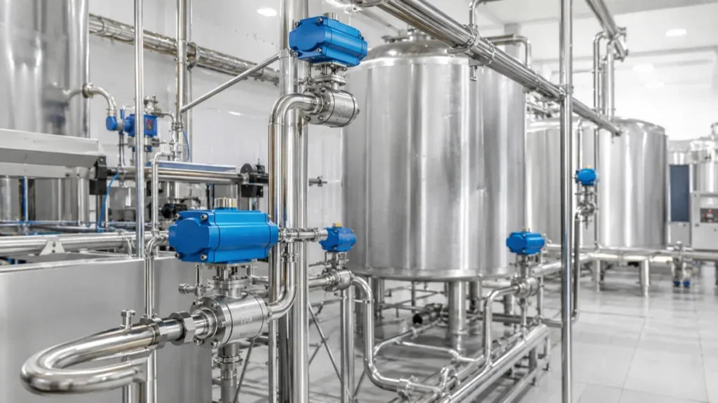
The Components in a Complete Pneumatic Ball Valve Package
The package has eight recurring parts. The valve and the actuator do the mechanical work. The solenoid valve, air preparation, and tubing deliver and switch the air. Feedback and controls tell the plant what the valve is doing, and the bracket and coupling hold everything together. Each part carries at least one decision that only the buyer can make.
| Valvola a sfera | Opens and closes the flow path | Fluid, size, end connection, body and seat material, operating pressure and temperature |
| Attuatore pneumatico | Turns compressed air into quarter-turn motion | Double acting or spring return, required action on air loss, torque requirement taken from the valve data |
| Elettrrovalvola | Switches air to the actuator on an electrical command | Coil voltage, air path in the de-energized state, manual override, wiring and connector |
| Filter/regulator or site air preparation | Cleans and regulates the air before it reaches the actuator | Site air quality, moisture control, the actuator manufacturer’s requirements |
| Limit switch box or position feedback | Reports the shaft position to the control system | Switch type and signal, enclosure rating required at the installation point |
| Tubing and fittings | Carries air between the components | Size, length, routing, material suited to the environment |
| Speed controls, if required | Slows the stroke in one or both directions | Which direction needs control, and the process reason for it |
| Mounting bracket and stem coupling | Connects the actuator to the valve stem | Mounting pattern and stem dimensions, checked against both the valve and the actuator |
Notice that the table contains no default numbers. Pressures, voltages, and torques differ between products and between plants, so every one of those blanks is a question to answer at the quotation stage, not after delivery. On the valve side, typical candidates for automation include 3-piece pneumatic ball valves for lines that need in-line maintenance and valvole a sfera pneumatiche con flangia for flanged piping systems.
Double Acting or Spring Return?
A double acting actuator uses air for both directions of travel. A spring return actuator uses air in one direction and a spring in the other, which gives it a defined action when the air supply is lost. This one choice shapes most of the rest of the package, so settle it first.
Double acting:
- Air pressure drives both the opening and the closing stroke.
- There is no spring inside.
- On loss of air, it does not move itself to a predetermined safe position.
- The valve position after an air failure cannot be assumed. It depends on trapped air, friction, and the load from the process.
Spring return:
- Air drives one direction; the spring drives the failure direction.
- Depending on how the actuator and valve are assembled, the package can be built as fail-open or fail-close. Spring return does not automatically mean fail-close.
- The valve rotation direction, the spring direction, the mounting orientation, and the actual behavior in a test all need to be confirmed before the package is accepted.
How to size the torque, how much margin to allow, and how to define the fail position for your process are covered in the Guida alla scelta degli attuatori per valvole.
The Solenoid Valve Decides How Air Is Switched
The solenoid valve is the electrical gateway of the package. When the control system energizes or de-energizes the coil, the solenoid changes which air paths are open, and the actuator moves accordingly. A solenoid that does not match the actuator, or the plant’s electrical supply, stops the whole package from working.
Confirm these points before ordering:
- Whether the actuator is double acting or spring return, because the two need different solenoid functions.
- The air path in both the energized and the de-energized state, so the valve does what the process expects in each state.
- The coil voltage. Voltages differ between plants and control systems, so there is no safe default. State it in the request for quotation.
- Whether a manual override is required for commissioning and maintenance.
- The wiring method and connector type expected at the installation point.
- Any environmental or hazardous-area requirement. Area certifications belong to each individual component, so the solenoid and any switches must be checked item by item against the classification of the installation area. International schemes such as IECEx, the IEC system for certifying equipment used in explosive atmospheres, certify individual devices, not the assembled package.
A NAMUR-style mounting interface simplifies installation on many actuators, but it does not guarantee that any solenoid fits any actuator. The specific combination still has to be verified.
Air Supply Quality and Capacity
The actuator can only be as reliable as the air behind it. The pressure that matters is the pressure available at the actuator while it is stroking, not the nameplate figure at the compressor on the other side of the plant.
Confirm wit
A common reference point when specifying air cleanliness is ISO 8573-1, the international standard that defines purity classes for compressed air. Which class a given actuator actually needs is stated by its manufacturer, so quote the standard together with the manufacturer’s documentation rather than on its own.
Position Feedback Is Not the Same as Shutoff Confirmation
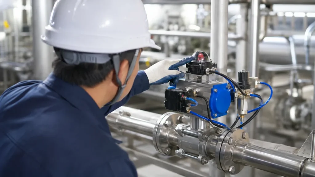
A limit switch box normally reports the position of the actuator shaft, typically at the open and closed ends of travel. That is useful information for the control room, but it is position feedback, nothing more.
A closed signal from the limit switch box does not prove that:
- the seat is sealing without internal leakage,
- the valve body is free of external leakage,
- flow in the line has actually stopped, or
- the mechanical coupling between actuator and valve has not come loose.
If the process requires confirmation of flow or of sealing, that confirmation has to come from a suitable process measurement or testing method, not from the switch box alone.
Speed, Water Hammer and Process Risk
How fast a pneumatic package strokes is not a fixed property of the valve. It is the combined result of the actuator size, the air pressure and flow available, the tubing, the solenoid capacity, any speed controls installed, and the load the valve itself presents.
Fast operation is often listed as an advantage of pneumatic actuation, but it is not always one. On liquid lines, closing too quickly can raise the risk of water hammer, the pressure surge that follows a sudden stop of flowing liquid. The effect is described in more detail in the article on water hammer in building piping systems. When the stroke speed needs to be adjusted, base the adjustment on an analysis of the system and on the specifications of the actual components. A generic closing time in seconds would be meaningless, so none is given here.
Controls and PLC Integration
The package eventually answers to a control system, and the interface between the two is where many commissioning surprises come from. Confirm each of the following with the people responsible for the controls:
- The command signal that will drive the valve.
- The solenoid voltage, matched to what the control panel actually supplies.
- Position feedback: dry-contact switches or another type, as the control system requires.
- How open and closed indication will be displayed and used.
- Alarm behavior when the valve does not reach the commanded position.
- Whether a local manual override is required.
- What the package must do when electrical power is lost.
- What the package must do when air is lost.
No combination of valve, actuator, solenoid, and controller should be assumed to work together out of the box. The valve package and the control side have to be specified against each other, in writing, before the order.
Commissioning Checks Before the Line Goes Live
When the package is installed, walk through a short functional check before the line carries process fluid. Every item below is something buyers have been caught by:
- The valve and actuator rotation directions match.
- The commanded open and closed positions are correct from the control room.
- The spring return fail direction is the one the process requires.
- The solenoid’s de-energized state produces the intended valve state.
- The limit switch signals match the actual valve positions.
- The behavior on air loss and on power loss has been tested, not assumed.
- The stroke speed does not create an unacceptable response in the system.
- The mounting bracket and stem coupling remain aligned after operation.
- External leakage inspection follows the site procedure.
Carry out these checks under your site’s own procedures. Never open or adjust a pressurized assembly.
RFQ Checklist for a Pneumatic Ball Valve Package
A request for quotation that includes the points below lets a supplier propose a matched package instead of a bare valve. Copy this list into your inquiry:
- Fluido e concentrazione
- Operating pressure and temperature
- Dimensioni della valvola e tipo di attacco
- Required valve body and seat material
- Operating frequency
- Available air supply
- Double acting, or the required fail-open / fail-close action
- Solenoid voltage
- Control and feedback requirements
- Ambient environment
- Hazardous-area or project certification requirements
- Desired accessories
- A P&ID or a simple operating sequence, if available
Domande frequenti
Quali componenti sono necessari per un kit completo di valvole a sfera pneumatiche?
Come minimo: la valvola a sfera, un attuatore pneumatico, un’elettrovalvola per la commutazione dell’aria, il sistema di trattamento dell’aria e le tubazioni, una staffa di montaggio con raccordo dello stelo e un sistema di retroazione di posizione, qualora il sistema di controllo debba rilevare lo stato della valvola. Altrettanto importante è una decisione che non riguarda affatto un componente: cosa deve fare la valvola in caso di interruzione dell’aria o dell’alimentazione elettrica. Verificare tutti questi aspetti prima di effettuare l’ordine.
Un attuatore a doppio effetto mantiene la propria posizione in caso di perdita di aria?
No, non si può dare questo per scontato. Un attuatore a doppio effetto non è dotato di molla, quindi in caso di perdita di aria non spinge la valvola in alcuna posizione prestabilita. La posizione finale della valvola dipende dall'aria intrappolata, dall'attrito e dal carico del processo. Se il processo richiede una posizione definita in caso di interruzione dell'aria, specificare un attuatore con ritorno a molla o un'altra soluzione ingegnerizzata e verificare il comportamento durante la messa in servizio.
Il ritorno a molla è sempre di tipo "fail-close"?
No. Un attuatore a molla di ritorno aziona la valvola in una direzione in caso di perdita di aria, ma il fatto che tale direzione sia di apertura o di chiusura dipende dal modo in cui l’attuatore e la valvola sono assemblati e montati. Esistono sistemi a molla di ritorno con apertura di sicurezza, che a volte sono esattamente ciò di cui il processo ha bisogno. Verificare sempre il senso di rotazione, l’azione della molla e l’orientamento di montaggio, quindi verificare la direzione effettiva di apertura in caso di guasto mediante un test.
Un finecorsa dimostra che la valvola è a tenuta stagna?
No. Una scatola dei finecorsa segnala normalmente la posizione dell’albero dell’attuatore, in genere alle estremità di apertura e chiusura della corsa. Non conferma che la sede sia a tenuta senza perdite interne, che il corpo sia privo di perdite esterne o che il flusso si sia effettivamente arrestato. Inoltre, non è in grado di rilevare un accoppiamento allentato dello stelo. Se il processo richiede la verifica della chiusura, utilizzare un metodo di misurazione o di collaudo adeguato.
È possibile utilizzare una valvola a sfera pneumatica per un controllo preciso della portata?
A standard on/off pneumatic ball valve package is not a precise flow control device. It is built to move between fully open and fully closed on command. Holding an intermediate position accurately calls for a different arrangement, such as a positioner-equipped control package, and a different evaluation of the valve and actuator. If your process needs modulation, describe that requirement in the inquiry instead of ordering an on/off package.
What information should I send for a quotation?
Send the fluid and its concentration, operating pressure and temperature, valve size and end connection, required body and seat material, operating frequency, your available air supply, the required action on air loss, the solenoid voltage, control and feedback requirements, the ambient environment, any hazardous-area or project certification requirements, desired accessories, and a P&ID or a simple operating sequence if available. With this list, a supplier can propose a complete matched package instead of a bare valve.
Ready to specify a package? Gather the items from the RFQ checklist above and send them through the Yzng Trong contact page. We will confirm whether the valve, actuator, solenoid valve, feedback devices, and control requirements can be combined into a package that fits your line, and tell you plainly if something does not fit.