
TL;DR / Quick Reference Summary
| Screen | Nominal opening | Millimetres | Inches | First engineering check |
|---|---|---|---|---|
| 20 меш | ≈840 µm | ≈0.840 mm | ≈0.0331 in | Coarse debris capture with more open area and lower clogging tendency |
| 60 меш | ≈250 µm | ≈0.250 mm | ≈0.0098 in | Medium capture where downstream passages require finer protection |
| 100 меш | ≈150 µm | ≈0.150 mm | ≈0.0059 in | Fine capture only where the system can accept higher fouling and pressure-drop risk |
These are useful nominal references, not guaranteed apertures for every screen. Mesh count describes how many openings occur per linear inch; it does not define wire diameter, weave, open area, screen strength or the assembled strainer’s flow coefficient. ASTM E11 controls nominal apertures and tolerances for test-sieve cloth, while an industrial Y-strainer screen must be confirmed against its supplier’s actual construction. The practical rule is simple: select the coarsest screen that still protects the smallest critical downstream passage. Choosing by mesh number alone can produce excessive differential pressure (ΔP), cavitation at a pump suction or inadequate equipment protection.
A disciplined selection sequence prevents most mistakes. First, obtain the allowable particle size from the pump, valve, meter or nozzle manufacturer. Second, identify the contaminant size distribution and expected loading, including start-up debris. Third, shortlist a screen aperture and calculate clean loss at maximum flow. Fourth, repeat the hydraulic check at the planned cleaning trigger. Finally, verify that the screen and support assembly can withstand the supplier’s stated differential-pressure limit. If any input is missing, treat the mesh as provisional. Do not purchase a finer element to compensate for missing process data.
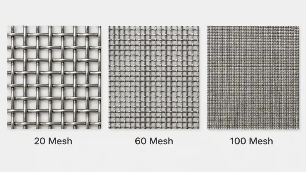
Comprehensive Y-Strainer Screen Conversion Chart
The table below uses common nominal plain-weave references. Actual openings can vary with wire diameter and weave, so specify an aperture in microns when the allowable particle size is a hard limit. ASTM E11-24 defines opening tolerances for test sieves; it does not automatically certify an industrial strainer screen.
| Сетка | Microns | мм | Inches | Screen type / structure | Typical industrial application |
|---|---|---|---|---|---|
| 10 | 2,000 | 2.00 | 0.0787 | Perforated plate or heavy woven wire | Large weld slag and commissioning debris |
| 12 | 1,680 | 1.68 | 0.0661 | Perforated plate or heavy woven wire | Coarse mill scale and pipe rust |
| 14 | 1,410 | 1.41 | 0.0555 | Perforated plate or heavy woven wire | Coarse pre-straining |
| 16 | 1,190 | 1.19 | 0.0469 | Perforated plate or heavy woven wire | General pipeline debris |
| 18 | 1,000 | 1.00 | 0.0394 | Heavy woven wire, often supported | Coarse pump protection |
| 20 | 840 | 0.840 | 0.0331 | Woven liner with support cylinder | Pump suction and general pipe debris |
| 25 | 710 | 0.710 | 0.0280 | Woven liner with support cylinder | Coarse sand and scale |
| 30 | 590 | 0.590 | 0.0232 | Woven liner with support cylinder | Pump and utility-water protection |
| 35 | 500 | 0.500 | 0.0197 | Woven liner with support cylinder | Fine pipe rust and larger sand |
| 40 | 420 | 0.420 | 0.0165 | Woven liner with support cylinder | Pump protection where tighter capture is justified |
| 45 | 354 | 0.354 | 0.0139 | Woven liner with support cylinder | General process pre-straining |
| 50 | 297 | 0.297 | 0.0117 | Woven liner with support cylinder | Meters and larger control passages |
| 60 | 250 | 0.250 | 0.0098 | Woven liner with support cylinder | Control valves, pilots and medium sediment |
| 70 | 210 | 0.210 | 0.0083 | Woven liner with support cylinder | Smaller pilot passages and instrumentation |
| 80 | 177 | 0.177 | 0.0070 | Woven liner with support cylinder | Solenoid valves and fine control passages |
| 100 | 149 | 0.149 | 0.0059 | Fine woven liner with support cylinder | Fine nozzles, meters and instrumentation |
| 120 | 125 | 0.125 | 0.0049 | Fine woven liner with support cylinder | Fine process particulates |
| 140 | 105 | 0.105 | 0.0041 | Fine woven liner with support cylinder | Small spray passages where specified |
| 170 | 88 | 0.088 | 0.0035 | Fine woven liner with support cylinder | Precision nozzle protection |
| 200 | 74 | 0.074 | 0.0029 | Fine woven liner with support cylinder | Very small orifices where the device maker requires it |
The application column is a screening shortlist, not a purchase specification. Start with the downstream equipment maker’s maximum allowable particle size, then check flow, clean ΔP, expected debris loading and maintenance access.
Beyond the Chart: Why Mesh Count ≠ Guaranteed Filtration
Mesh count is only the pitch count. In a plain square weave, each pitch contains one opening plus one wire diameter:
Opening (µm) ≈ (25,400 / Mesh) − Wire diameter (µm)
For the same mesh count, a thicker wire makes a smaller aperture. It also occupies more of the screen face. The approximate geometric open area is:
% Open area = [Opening / (Opening + Wire diameter)]² × 100
Consider two 60-mesh screens. Their pitch is 25,400 / 60 = 423.3 µm.
- With 0.19 mm (190 µm) wire, the opening is about 233.3 µm and the open area is about 30.4%.
- With 0.16 mm (160 µm) wire, the opening is about 263.3 µm and the open area is about 38.7%.
Both screens are sold as 60 mesh, yet the thinner-wire version has a roughly 13% larger aperture and about 27% more open area relative to the thicker-wire version. It may start with less resistance, but its wire may also have less mechanical margin. The thicker wire may be stronger, but its lower open area raises face velocity through each opening.
Do not convert that comparison directly into a fixed ΔP value. The assembled result also depends on total screen area, body geometry, fluid density and viscosity, flow rate, fouling state and the supplier’s Kv/Cv data. For a real line, obtain the clean-strainer pressure-loss curve for the proposed body size and screen, then calculate at normal and maximum flow. Record that clean baseline during commissioning.
Construction Mechanics: Perforated Plate vs. Woven Wire Mesh
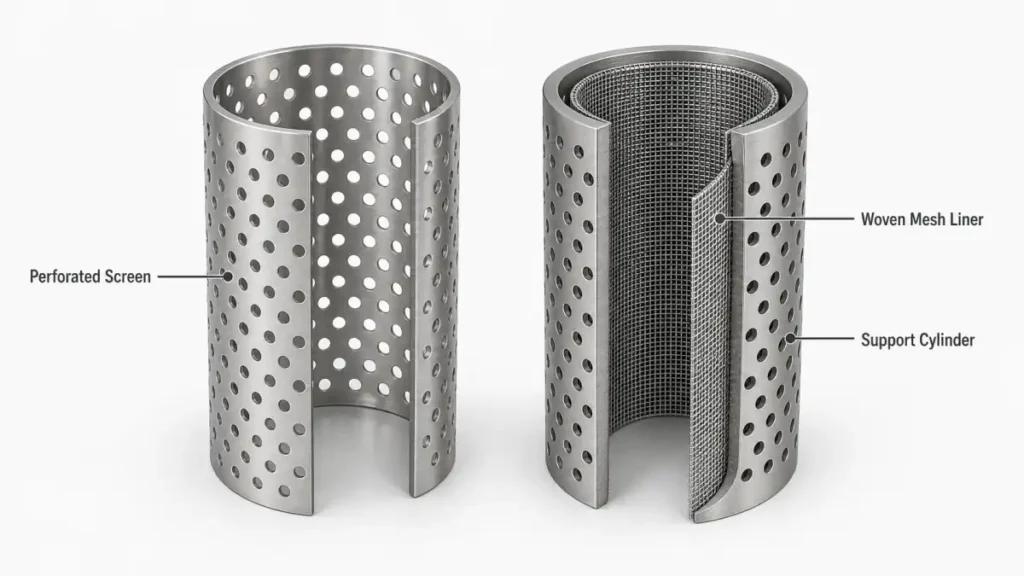
A perforated screen is made by punching holes into sheet metal and rolling it into a cylinder. It is stiff and durable, but it is normally coarse. Spirax Sarco’s strainer guidance describes typical perforated openings of about 0.8 to 3.2 mm. A perforated screen by itself is therefore a practical choice for general debris, particularly when the required hole is above roughly 1 mm.
Fine filtration needs a different assembly. Woven wire can provide apertures down to the tens of microns, but a thin mesh liner should not be expected to carry a severe differential-pressure spike by itself. For 60, 100 or finer mesh in Y-strainer duty, specify a woven liner laid against a perforated support cylinder. Flow direction must press the mesh toward its support, not peel it away. Confirm the liner attachment, support perforation, collapse rating and replacement-screen construction with the supplier.
The distinction matters during blockage. A supported liner transfers load into the backing cylinder. An unsupported or incorrectly oriented liner can deform, tear or pull away from its seam. The body may remain leak-tight while the filtration function has already failed.
Keep three area terms separate. Gross screen area is the outside surface of the cylindrical element. Open area is the percentage of the woven face that is aperture rather than wire. Effective straining area is the usable open area after deducting seams, supports and portions shielded by the body. A large cylinder made from low-open-area mesh can still be restrictive, while a compact element may foul quickly even if its wire cloth has a high open area. Ask for the assembled strainer’s pressure-loss data instead of estimating performance from a mesh coupon alone.
Matching Mesh Sizes to Downstream Equipment Protection
The equipment being protected sets the upper limit on particle size. The piping system sets how fine a screen it can operate without unacceptable ΔP or maintenance. Resolve both sides before choosing a mesh.
| Downstream equipment | Practical starting range | Почему | Required engineering check |
|---|---|---|---|
| Centrifugal pump suction | 20–40 mesh preferred as a first review range | Coarser screens retain weld slag, scale and rust while consuming less suction pressure than a fine screen | Include clean and dirty strainer loss in NPSHa; keep the pump maker’s required NPSH margin |
| Control valve / solenoid valve | 60–80 mesh when seats, pilots or small ports need it | Finer capture reduces the chance of debris lodging in trim or pilot passages | Use the smallest internal passage and maker’s filtration requirement, not valve line size |
| Steam trap / boiler auxiliary line | Often 20–60 mesh, selected for the trap and debris | Scale and magnetite can block seats; thermal cycling also loads the screen, gasket and cap joint | Confirm steam pressure-temperature suitability, screen material, installation orientation and blowdown procedure |
| Flow meter / fine spray nozzle | 100–200 mesh when the device manufacturer specifies that range | Small bores can plug with fine sand, PTFE fragments or process solids | Treat 100–200 mesh as mandatory only where the meter or nozzle maker requires it; verify clean ΔP and cleaning frequency |
On a pump suction, strainer loss directly reduces net positive suction head available (NPSHa). Grundfos explains that inadequate inlet pressure can let the liquid reach vapour pressure and cavitate. A 100-mesh screen may look safer on a particle chart while making the pump less safe hydraulically. Check the pump curve at maximum expected flow and include the dirty-screen condition or alarm setpoint in the NPSH calculation.
For nozzles, match the screen to the orifice rather than using a universal number. Spraying Systems Co. states that a liquid strainer should remove particles larger than the nozzle orifice will pass. Its equipment guidance includes recommendations from 30–50 mesh to 200 mesh depending on nozzle design. That variation is why the nozzle data sheet controls.
Steam service needs similar discipline. Start the system gradually, verify the permitted pressure and temperature for the assembled strainer, and inspect the screen and sealing parts after thermal cycling. “800 WOG” is a cold, non-shock water, oil and gas pressure designation; it is not an 800 psi steam rating.
Pressure Drop (ΔP), Clogging Dynamics, and Screen Collapse
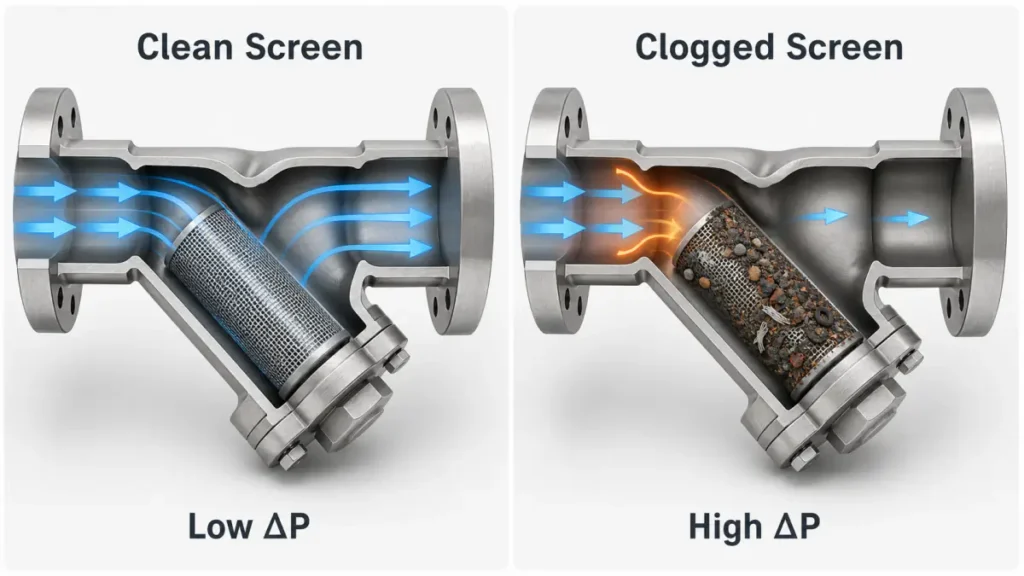
A clean screen begins with a pressure drop set by flow and open area. As debris covers the surface, the remaining openings carry more velocity. ΔP then rises nonlinearly, and the rise can accelerate near the end of a cleaning cycle. Trend ΔP at a comparable flow rate; a reading taken at half flow cannot be compared directly with the full-flow baseline.
Use two pressure taps or gauges, one upstream and one downstream. At commissioning, record clean ΔP at normal and maximum operating flow. Set the maintenance trigger relative to that baseline. As a practical starting point, schedule cleaning or controlled blowdown when ΔP rises about 5–8 psi (0.35–0.55 bar) above the clean value, provided the equipment supplier and process allow it. This is a trigger, not a universal screen limit. Low-NPSH pump systems, fragile screens or sensitive control loops may require action much earlier.
The range is consistent with Eaton’s Y-strainer manual, which calls for cleaning after a 5–10 psi increase on the covered models. The same manual warns not to exceed 20 psi across those specific screens. Do not transfer that 20 psi value to another manufacturer’s screen; obtain the permitted differential pressure for the actual assembly.
If ΔP keeps climbing, the mesh can dish inward, separate at a seam, tear or collapse against the support. A sudden drop in ΔP is not always good news. If flow recovers without cleaning, the screen may have blown out and opened a bypass path through the damaged element. The body can look normal while rust, scale and gasket debris travel directly to the pump, valve or nozzle.
After each cleaning, inspect the screen against light for holes, tears, loose seams and permanent deformation. Also inspect the support cylinder, cap seal and seating surfaces. A screen with a local tear should be replaced, not returned to service because most of its area still looks intact.
Plan the maintenance method before commissioning. Route blowdown to a safe closed drain or collection point compatible with the fluid, temperature and pressure. If the cap must be opened, isolate both sides, depressurise, drain and verify zero energy before loosening it. Clean from the clean side toward the dirty side so debris is pushed out of the openings rather than deeper into the weave. Record the debris type, ΔP before cleaning and operating hours since the previous service. A shortening interval signals a process change, start-up contamination, an undersized strainer or a screen that is finer than the equipment requires.
How to Specify the Right Y-Strainer (7-Point Inquiry Checklist)
Send the following seven values with an inquiry. They let the supplier assess material, mesh, body size and maintenance needs as one system.
- Fluid and compatibility: Name the fluid, concentration, pH, solids and chloride content. Include cleaning chemicals and upset media.
- Температура: State normal, maximum and minimum temperature, plus steam or thermal-cycling conditions.
- Pressure class: Give normal pressure, design pressure, surge or water-hammer exposure and the applicable piping code.
- Flow rate: Provide normal, minimum and maximum flow, fluid density and viscosity where relevant.
- Pipe size and connection: State nominal size and the exact thread or flange standard. “Threaded” alone is not enough.
- Target particle size: Give the maximum particle that downstream equipment may receive, in microns, plus the proposed mesh and wire diameter if known.
- Maximum allowable ΔP: Give the clean-loss budget, alarm or cleaning trigger, screen differential-pressure limit and required cleaning interval.
For threaded services that fit its published envelope, the Yzng Trong Y-type strainer provides a 316 stainless steel body, PT threaded connections from 1/4″ to 3″, an 800 WOG body rating and 20, 60 or 100 mesh SUS 316 screens. Use those details as a shortlist, then check the seven line conditions above. NPT and PF threads, temperature suitability, chemical compatibility, the exact screen construction and the allowable differential pressure should all be confirmed on the quotation.
Frequently Asked Questions (FAQs)
Является ли сетка 60 меш всегда лучшим выбором для общего назначения?
No. It is the middle of the common 20/60/100 options, not an engineering default. A 60-mesh screen can be too fine on a pump suction with little NPSH margin and too coarse for a small nozzle. Choose from the downstream particle limit, then verify flow and maintenance.
What happens if the mesh is too fine?
The clean pressure drop increases, the screen captures more of the incoming solid load and the cleaning interval shortens. On a pump suction, lost inlet pressure can reduce NPSHa and cause cavitation. If maintenance is delayed, the screen can deform or blow out. A finer mesh improves protection only when the system can keep it clean and the equipment needs the smaller aperture.
How do I convert mesh to microns mathematically?
For a plain square weave:
Opening (µm) ≈ 25,400 / mesh count − wire diameter (µm)
Mesh count without wire diameter is not enough. For example, 60 mesh has a 423.3 µm pitch. Subtracting a 173 µm wire gives an opening near 250 µm; another wire diameter gives another opening. Use the screen maker’s measured or specified aperture for critical service.
Does 316 stainless steel mesh resist all chemical media?
No. Molybdenum gives 316 better resistance to chlorides and reducing acids than 304, but it does not make 316 immune. Hot or concentrated chloride service can cause pitting or stress-corrosion cracking, and strong reducing acids can exceed the alloy’s useful range depending on concentration, contamination and temperature. The Институт никеля recommends choosing material for the specific service environment. Confirm compatibility using the fluid name, concentration, chloride content, temperature, aeration and cleaning chemistry.