
Why I Keep Reaching for a Three-Way Valve
The first time a process engineer handed me a P&ID with two separate two-way valves, a tee, and a tangle of pipe all doing the job of one part, I did what any tired field tech does at 6 a.m. on a cold platform: I sighed. There was a cleaner answer sitting in my van the whole time. A single three-way valve would have replaced that whole assembly, cut two flanged joints out of the leak-path budget, and saved the client the cost of an extra actuator and its wiring. That morning is basically why I write guides like this one, because the part that fixes the problem is rarely the part people are looking at.
A three-way valve is one of those components that looks simple and quietly does something clever. Instead of just opening and closing a single line, it routes media between three ports. You can send one inlet to either of two outlets, merge two inlets into one outlet, or use the body as a compact bypass loop. When people search for a 3-way ball valve, they usually already know they need to switch or divert flow. What they are really asking is which port style to choose, how to actuate it, and what is going to bite them six months after commissioning when the warranty paperwork is filed and everybody has moved on. I have been on the wrong end of all three questions, so let me walk through the whole thing the way I would explain it to a colleague over coffee, without the catalog gloss.
This guide is long on purpose. Half an hour here beats two days troubleshooting a valve that was specified wrong, and that second scenario always seems to land during a production shutdown with everyone watching. We will cover how the ball and ports move, the L-port versus T-port decision that trips up even experienced engineers, the choice between manual, pneumatic, and electric operation, the materials that survive your media, the sanitary and vacuum variants that change the rules, and the lifecycle math behind automation. Tables, honest warnings about what these valves cannot do, and links to the actual hardware so you can read real specifications instead of my hand-waving.
What a 3-Way Ball Valve Actually Does
Before we argue about port styles, let me make sure we are picturing the same part, because half the confusion in valve selection comes from two people using the same words for different mental images. Strip away the actuator and the body, and you have a hollow metal ball sitting between two seats, with a bore drilled through it. Rotate the ball a quarter turn and the bore lines up with different ports. That is the entire trick. The genius is in how that bore is shaped, because the bore geometry is what turns a plain shut-off device into a flow router. This section breaks the part into the three pieces that actually matter on a datasheet.
The Ball, the Bore, and the Three Ports
A two-way ball valve has a straight bore: media goes in one side and out the other, and a quarter turn either lines the hole up or blocks it. A three-way design keeps the same quarter-turn ball but adds a third port and a bored ball that is shaped like an L or a T. Two of the ports usually sit in line with the main pipe run, and the third comes off at ninety degrees, often pointing down or to the side depending on how the body is cast. The body therefore looks less like a simple inline fitting and more like a tee with a valve mechanism living inside it.
Because the ball still only rotates ninety degrees in most designs, the operator motion feels identical to a normal valve. The difference is what happens inside. As the ball turns, the bore sweeps from one port to another, and there is a brief window mid-rotation where flow paths overlap or close depending on the port machining. That overlap behavior is the single most important thing to understand, and it is exactly why the L versus T choice matters so much. Get the bore shape right and the valve does precisely what your process diagram promised. Get it wrong and you will be chasing phantom cross-flow that nobody designed for, the kind of intermittent problem that makes operators distrust an entire system. The lesson I keep relearning is that on a three-way valve the geometry is the specification, not an afterthought.
L-Port vs T-Port: The One Decision People Get Wrong
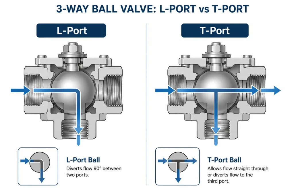
Here is the distinction in plain language. An L-port ball has a bore bent at a right angle, so it connects the center port to one of the two side ports at a time. It is a selector. You are choosing path A or path B, and the third port is shut. A T-port ball has a bore shaped like the letter T, so it can connect the center port to one side, to the other side, or to both side ports simultaneously. It is a combiner and a diverter, capable of mixing or splitting flow depending on which way the media is travelling.
People reach for a T-port because it sounds more flexible, then discover during commissioning that it will not give them clean isolation between two tanks, because there is a rotation position where all three ports talk to each other. Other people specify an L-port for a mixing duty and cannot understand why they never get a blend, no matter how they set the handle. Both mistakes come from the same root cause: assuming the word “three-way” means one universal behavior. It does not. The bore shape defines the behavior, and the bore shape is a decision you make before you order, not something you can adjust on site. The table below is the cheat sheet I wish someone had taped to my toolbox years ago.
| Feature | Porta L | Porta T |
|---|---|---|
| Bore shape | 90-degree elbow | T-shaped, three legs |
| Primary job | Selecting one path of two (diverting) | Diverting, combining, or mixing flow |
| Can connect all three ports at once? | No | Yes, in certain positions |
| Ideale per | Switching a source between two destinations | Bypass loops, merging two feeds, blending |
| Common mistake | Expecting it to mix two streams | Expecting hard isolation between side ports |
| Handle positions | Usually two working positions | Often three or four working positions |
One practical note from the field: always confirm the actual flow diagram printed on the valve body or datasheet rather than assuming. Manufacturers do not all machine their L and T balls identically, and the position of the handle relative to the open port can differ between brands and even between product lines from the same maker. I have seen two valves built to the same drawing behave differently because the stop pin was set for a different sequence, which turned a routine valve swap into an afternoon of head-scratching. Trust the stamped diagram, not your memory, and physically verify the flow path with low-pressure air or water before you hand the system over.
Where the Pressure Rating Comes From
Most of the stainless three-way valves I install for general process work carry a 1000 WOG rating, which stands for Water, Oil, Gas at a cold working pressure of 1000 psi. That number describes the non-shock cold working pressure of the body and is a useful shorthand, but it is not the whole story, and treating it as a guaranteed ceiling is how people get into trouble. The seat material, the temperature, and whether your service is pulsing or steady all chip away at that headline figure. A valve rated 1000 WOG at room temperature with a PTFE seat will not hold 1000 psi if you push it to its temperature ceiling, because polymer seats soften as they warm and lose their ability to resist extrusion.
If you want the real envelope, you look at the pressure-temperature curve, and for the underlying engineering logic the standards bodies are the right place to read rather than a forum post. The ASME B16.34 standard covers pressure-temperature ratings for valves, and the floating-ball design itself is described in the industry references catalogued by the American Petroleum Institute. I am not telling you to memorize the codes. I am telling you that the WOG number is a starting point, not a promise, and the seat is usually what gives out first when conditions get aggressive. When in doubt, derate, and confirm the figure against the manufacturer’s published curve for your exact temperature.
Flow Paths Explained: Diverting, Mixing, and Switching
This is where the three-way valve earns its keep. It is also where I have watched good engineers talk past each other, because “mixing” can mean three different things in the same meeting. Once the vocabulary is straight, the port-style choice almost makes itself. A three-way valve really gets asked to do three jobs, and each one has a preferred port style and a couple of traps worth knowing before you commit to a body casting. One at a time.
Diverting Flow: One In, Two Out
Diverting is the bread-and-butter duty. You have a single supply and you want to send it to destination A or destination B. Think of a heat-transfer skid where hot oil either goes through a heat exchanger or bypasses it to control outlet temperature, or a sampling line that normally runs to a process tank but can be swung to a drain for cleaning between batches. This is L-port territory. The L bore connects the common inlet to whichever outlet you select, and the unused outlet is positively shut, with no sneaky leakage path to the line you are trying to isolate.
The reason I like an L-port here is that it gives you an unambiguous answer: flow is going to A, or flow is going to B, never a confusing trickle to both at once. If your process logic depends on clean separation, for example you genuinely cannot afford clean product leaking into a drain line for hygiene or yield reasons, the L-port’s hard shut-off is exactly what you want and it removes a whole class of contamination questions. For a typical diverting duty in stainless, a manual 3-way ball valve in 316 stainless handles the job without drama, and stepping up to a powered version later is just a matter of bolting an actuator onto the same body. Size the valve for the line and the flow you actually need, not for the convenience of matching an existing thread, and the diverting duty will be the most boring part of your project, which is the highest praise a valve can earn.
Mixing Flow: Two In, One Out, and Why I Am Cautious
Now for the duty that earns the most support calls and the most disappointed phone messages. Mixing means you take two inlets and combine them into a single outlet, and a T-port valve can physically do this. What it cannot do is blend with any precision. A ball valve is a quarter-turn, on-off device at heart. It is brilliant at full open and full shut and genuinely poor at the in-between positions, because the flow does not change in a nice linear way as you crack it open, and the seats are not designed to sit half-exposed to a fast stream for long. If you try to throttle a ball valve to get a steady 40-60 blend, you will wear the seat unevenly, you will get cavitation noise that sounds like gravel in the pipe, and your ratio will wander as the seat erodes.
So here is my honest position, and it has cost me sales before. Use a T-port three-way valve for combining two streams when you just need them joined, not metered to a tight specification. If you genuinely need a controlled blend ratio that holds over time, that is a control-valve problem with a positioner and a characterized trim, and a ball valve is the wrong tool no matter how the catalog photo makes it look. I would rather lose an order than have a client running a ball valve as a throttling device and cursing my name at the next shutdown when the seats are chewed up. For the underlying fluid behavior and why partial opening misbehaves, the flow coefficient reference at Engineering ToolBox is a clear, jargon-light primer that I have sent to more than one client to settle the argument.
Switching and Bypass Tricks
The third duty is everything in between: bypass loops, instrument isolation, lead-lag pump switching, and continuous-flow arrangements where you never want to dead-head a pump. A T-port shines here because that “all ports connected” position, which is a liability for isolation, becomes a genuine feature for a make-before-break switch. You can swing flow from one path to another without ever fully blocking the pump, which protects against the pressure spike that happens when you slam a deadhead shut. I have used this on duty-standby filter banks so the operator can switch to the clean filter while the dirty one is still passing flow, then isolate and service the dirty side without ever stopping production.
The trick is to map the handle positions to your written operating procedure and label them physically on the valve itself. A valve that can do four things is only useful if the operator at 3 a.m. knows which way the handle points for “bypass” without phoning the day shift. I print a small position card and zip-tie it to the actuator or stem. It is low tech and slightly ugly, but it has saved more than one batch and a fair amount of overtime. When the valve is automated, the same logic lives in the control narrative, and I always insist the failure position is written down in plain words, not just buried in a PLC tag description that nobody reads.
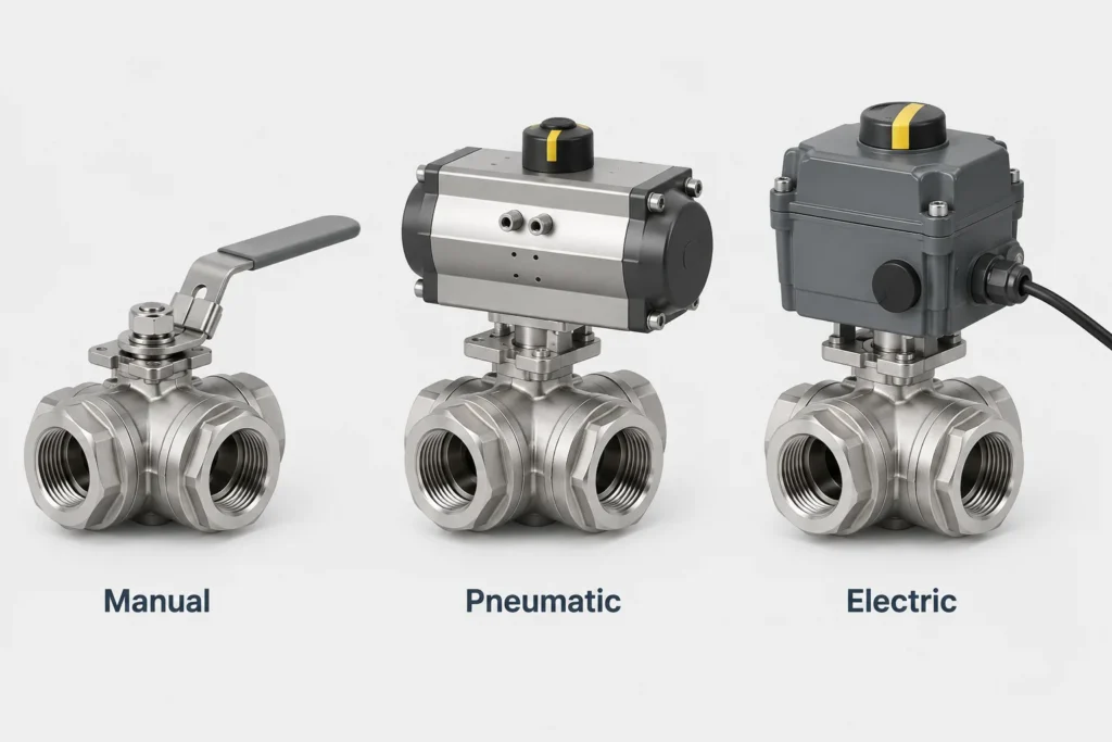
Manual, Pneumatic, or Electric? Choosing the Actuation
Once you have the port style settled, the next fork is how the valve gets turned. The body and ball can be identical across all three options; what changes is the thing sitting on top of the stem and how much it costs to own over the years. I have installed all three on the same skid in the same week, and the right choice almost always comes down to how often the valve cycles, whether you need remote or automatic control, and what utilities you already have on site. If you want the deeper dive on actuator selection specifically, including torque and sizing, I wrote a separate field guide to valve actuator selection that goes further than I can fit here.
Manual: The Honest Lever
A hand lever is cheap, reliable, and never loses power in a brownout. For valves that get switched occasionally, during a changeover, a cleaning cycle, or a seasonal reconfiguration, manual is genuinely the smart engineering choice, not a budget compromise you should feel guilty about. There is nothing to fail, nothing to power, nothing to commission, and an operator can feel the detents that mark each position through the handle. The downside is obvious: somebody has to walk to the valve and turn it, and on a three-way the multiple positions mean the operator has to actually understand the flow logic rather than just open or shut a single line.
For occasional-duty stainless service, a plain manual valve like the 316 stainless manual three-way ball valve covers most of what general process plants need, and the broader manual ball valve range gives you the two-way companions for the rest of the line so everything matches. My rule of thumb has stayed the same for years: if the valve cycles less than a few times per shift and an operator is routinely nearby, start with manual and only automate when you can write down a concrete reason, such as a safety interlock or a duty that genuinely happens too often for a person.
Pneumatic: Fast, Repeatable, and My Default for Cycling
When a valve cycles often, or needs to operate on a signal from a controller, a pneumatic actuator is usually where I land. Compressed air is already plumbed across most plants, the actuators are fast and rugged, and they handle frequent cycling far better than a tired human wrist ever will. With a three-way valve you do need to confirm the actuator has enough rotation and the correct cam or stops for your sequence, because some multi-position duties need more than a simple ninety-degree stroke and a mismatched actuator will only ever reach two of the positions you wanted.
The two configurations you will hear about are double-acting and spring-return. A double-acting actuator, written DA, uses air to drive the valve both ways and holds its last position if air is lost. A spring-return actuator, written SR, uses air to move one way and a spring to drive it back to a safe position when air or signal is lost, which is your fail-safe. For most diverting safety duties I specify spring-return so the valve defaults to the path that protects the process, for instance routing to a safe recirculation loop rather than a downstream vessel. A ready-to-install option such as the 316 stainless three-way pneumatic ball valve pairs the actuator with the valve from the factory so the torque and mounting are already matched, and the wider pneumatic ball valve category covers the in-line valves around it. Decide DA versus SR by asking one blunt question: when the air fails, where do I want this flow to go?
Electric: When You Have Wires but No Air
Electric actuators make sense where there is no compressed air, where you need precise position feedback for the control system, or where the valve is remote and you are already running cable to it for other instruments. They cycle slower than pneumatics, and you need to think about duty cycle and motor heat on frequently switched valves, because an electric actuator asked to cycle constantly will overheat and shorten its own life. But for a three-way valve that repositions a few times an hour under PLC control, an electric actuator is clean, quiet, and tidy, with no air lines to leak. The trade-off is fail-safe behavior: a plain electric actuator stays exactly where it is on power loss unless you add a battery backup or spring-return pack, which costs money and adds a maintenance item that itself needs checking. If failure position matters and you have air available, I lean pneumatic; if you only have power, electric with a clearly documented failure mode is the right answer. The general principles I apply across manual, pneumatic, and electric are laid out in my overview of ball valve types by actuation, which is worth a read before you finalize a skid design.
Materials and Seats: Matching the Valve to Your Media
The body and ball material is where a project either ages gracefully or rusts into a warranty conversation. Almost every three-way valve I specify is 316 stainless steel, and I want to be precise about why, because the internet is full of half-right advice that says “use 316 for acids” and then sends people down the wrong path. That is not the real trigger. The deciding factor between 304 and 316 stainless is chloride exposure and pitting risk. Chlorides, the kind you find in seawater, coastal air, brines, and many cleaning and sanitizing chemicals, attack the passive oxide layer on stainless and cause localized pitting that can perforate a wall long before general corrosion would. The molybdenum content in 316 is what resists that chloride pitting. So you choose 316 not because your media is vaguely “harsh” but because there are chlorides in play or because the consequences of a pinhole leak are serious enough that the upgrade is cheap insurance.
The seat is the other half of the equation, and on most general-service three-way valves it is PTFE. PTFE seals beautifully, shrugs off a huge range of chemicals, and gives that bubble-tight shut-off ball valves are loved for. Its limit is temperature: PTFE seats are typically good in the region of roughly minus 20 to 180 degrees Celsius, and they soften and lose pressure capability toward the top of that band. Always read the actual datasheet rather than trusting a round number from a guide like this one, because the seat rating, not the steel, is usually what caps your real service conditions. The table below is how I frame the material conversation with a client before anything gets ordered.
| Decision point | What pushes you up a grade | My default starting point |
|---|---|---|
| Body and ball material | Chlorides, marine or coastal air, brines, pitting risk | acciaio inossidabile 316 |
| Seat material | Wide chemical range, tight shut-off needed | PTFE, mind the temperature ceiling |
| Temperatura | Hot media near the seat’s upper limit | Confirm pressure-temperature curve before ordering |
| Hygiene or product contact | Food, beverage, pharma, clean-in-place | Sanitary tri-clamp body, 316, smooth finish |
| Vacuum or very low pressure | Process under vacuum, leak-tight to atmosphere | Dedicated vacuum-rated body and connections |
One more honest caveat on materials: stainless is not a magic shield, and selling it as one sets up a disappointment. If your media carries abrasive solids, even 316 will erode at the bore edges over time, and a ball valve’s seats do not love grit caught between the ball and the seat ring. In those cases I tell people up front that a ball valve is a reasonable choice with a shorter service interval, not a fit-and-forget part, and I would rather have that conversation at the quote stage than at the failure. Setting that expectation early is the difference between a happy repeat client and an awkward callback where everyone feels misled. The material choice is a risk decision as much as a chemistry one.
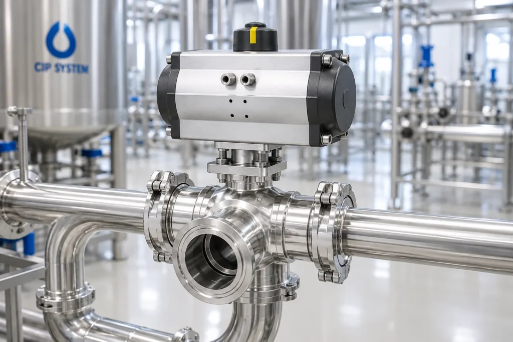
Sanitary and Vacuum Variants That Change the Rules
So far I have been describing general industrial service, threaded or welded into a steel line. Two specialized worlds change the rules enough that they deserve their own hardware, and it is worth understanding both even if your current project is neither, because the engineering reasoning carries straight over to anything where leakage or contamination is the real enemy. Those two worlds are hygienic processing and vacuum service.
In food, beverage, biotech, and pharmaceutical work, the enemy is not just corrosion but crevices. Anywhere product can sit and stagnate becomes a place for bacteria to grow, which is why hygienic valves use tri-clamp connections that take apart for inspection, smooth polished internal finishes that give bacteria nothing to cling to, and bodies designed to drain fully and be cleaned in place. A three-way valve is especially common on clean-in-place skids, where it switches a single line between product flow and cleaning solution so the same pipe can run both without a manual reconfiguration. For those duties the sanitary manual three-way ball valve with tri-clamp ends and its powered sibling, the sanitary pneumatic three-way ball valve, are built for that environment in 316 stainless. If your line touches potable water or food, the hygiene standards from bodies like 3-A Sanitary Standards and the materials guidance from NSF are the right references to read alongside the manufacturer datasheet, since they define what “sanitary” actually has to mean rather than leaving it as a marketing word.
Vacuum service flips the usual concern on its head. Instead of holding pressure in, you are stopping atmosphere from leaking in, and ordinary threaded connections are simply not built for that direction of sealing. Vacuum valves use NW/KF flange connections and seals chosen specifically to stay leak-tight against a pressure differential pulling the wrong way. When a process under vacuum needs to switch or isolate a line, a dedicated pneumatic three-way vacuum ball valve or its manual three-way vacuum counterpart in 316 stainless is the correct tool, and trying to save a little money with a standard threaded valve here is how you end up chasing a vacuum leak that you will never find with soapy water and a lot of patience. Match the connection type to the world your process actually lives in, and the specialized variants stop looking like an expensive upgrade and start looking like the only thing that works.
Cost, Lifecycle, and When Automation Pays for Itself
Let me talk money for a moment, because the purchase price of a valve is the smallest number in the whole decision and people anchor on it anyway. The real cost of a valve over its life includes installation labor, the actuator and its utilities, commissioning time, spare parts, and the downtime when it fails or gets serviced. A cheap valve that needs an operator to babysit it, or one that fails in the wrong position during a production run, is not cheap at all once you add up what it actually costs to own. I have watched a plant manager sign off on the lowest bid for a rack of valves, only to spend the saving ten times over in the first year on labor and lost batches, and the painful part is that the spreadsheet at purchase time looked like a win. The cost that matters is the one you pay over the whole service life, and it almost never lines up with the sticker.
Here is the rough logic I use. A manual valve has the lowest purchase and installation cost and effectively zero running cost, so for low-cycle duties it wins on lifecycle even though it needs a human. A pneumatic actuator adds purchase and air-supply cost but pays for itself quickly on any valve that cycles often, because operator time is expensive and inconsistent, and because automated cycling is repeatable in a way a person at the end of a long shift is not. An electric actuator sits in between on running cost but higher on purchase, and it earns its place when you have no air or genuinely need the position feedback for control. The break-even is rarely about the valve and almost always about how many times it moves and how expensive a wrong position is.
The other half of lifecycle thinking is serviceability. A three-way valve with a replaceable seat kit and a standard actuator mounting will cost you far less over ten years than a sealed unit you have to scrap and re-buy, even if the sealed unit is cheaper on day one. When I compare two options, I always ask whether I can get seats and seals for it in five years, and whether the actuator bolts to a standard pattern so I am not locked into a single supplier forever. Specify for the decade, not the purchase order, and the three-way valve becomes one of the cheapest pieces of reliability you can buy.
Installation, Sizing, and the Mistakes I See Most
I could fill a notebook with three-way valve installation stories, most of them ending with someone saying “but it worked on the drawing,” but the failures almost all trace back to a handful of avoidable mistakes. Let me hand you the short list so you can skip the expensive lessons. None of this is exotic; it is just the stuff that gets forgotten under schedule pressure when the crew wants to go home and the valve is the last item on the punch list.
First, orientation. On a three-way valve the third port is not interchangeable with the other two, and the flow diagram assumes a specific port is the common one. Plumb it backwards and your “select A or B” valve quietly becomes “select common or nothing,” which you will not discover until you are commissioning the line under pressure. Before a single thread is tightened, match the port markings on the body to your P&ID and confirm which port is common. Second, support and stress. A three-way body is heavier and has more ports hanging off it than a simple inline valve, especially once an actuator is bolted on top, and that mass acts like a lever. Unsupported, it puts bending load on your pipe and on the valve stem, which leads to leaks at the threads and premature stem-seal wear. Support the actuator and the valve body; do not let the assembly hang on the pipe alone and hope for the best.
Third, sizing for the duty, not the handle. The temptation is to match the valve to the existing pipe thread and move on, but the bore through a three-way ball is often smaller than the nominal size suggests, and the right-angle path adds flow resistance that a straight valve does not. If flow capacity matters to your process, check the flow coefficient and size up if needed rather than discovering a bottleneck at startup when the line will not deliver rated flow. Fourth, and this is the one I will repeat until I am hoarse, do not use a ball valve as a throttling device. I covered why in the mixing section, but it bears repeating because partial-open operation is the single leading cause of premature seat failure I see in the field, full stop. Open or shut; let a proper control valve do the modulating. Treat those four rules as non-negotiable and your installation will outlive the warranty by years rather than generating callbacks. Professional standards organizations such as the International Society of Automation publish good background reading if you want to formalize your selection and installation process beyond field rules of thumb, and it is worth doing once for a process you will build many times.
Domande frequenti
What is the difference between an L-port and a T-port three-way valve?
An L-port has a bore bent at ninety degrees, so it connects the common port to one of two side ports at a time, making it a selector that gives clean isolation of the unused port. A T-port has a T-shaped bore that can connect the common port to either side or to both at once, making it suitable for combining flow or for make-before-break switching, but it cannot give you hard isolation between the two side ports because of that all-connected position. Choose L-port for “A or B” selection where separation matters, and T-port for combining or bypass duties. If you need a powered version of either, the three-way pneumatic ball valve is offered to suit both port styles.
Can a 3-way ball valve be used for mixing or blending?
It can physically combine two streams into one, but it cannot blend them to a precise ratio. A ball valve is fundamentally an on-off device and performs poorly at partial openings, where it causes cavitation and accelerated seat wear that makes any ratio drift over time. Use a T-port valve to merge streams when you only need them joined, not metered. If you need a controlled blend ratio that holds, that is a job for a dedicated control valve with a positioner, not a ball valve, no matter how convenient the single-body solution looks. For sanitary mixing and switching duties on a clean-in-place skid, the sanitary pneumatic three-way ball valve handles the combining role well within those limits.
What does the 1000 WOG rating actually mean?
WOG stands for Water, Oil, Gas, and 1000 WOG means the valve body is rated for 1000 psi cold working pressure in those media under non-shock conditions. It is a useful headline figure but not the full picture: the PTFE seat and elevated temperature both reduce the usable pressure, so a valve rated 1000 WOG at room temperature will hold considerably less as it heats up toward the seat’s limit. Always check the pressure-temperature curve on the datasheet for your actual operating temperature rather than assuming the headline number. A standard threaded option like the manual 3-way ball valve carries the 1000 WOG rating for general process service.
Should I choose manual, pneumatic, or electric actuation?
Pick manual for valves that cycle rarely and have an operator nearby, since it is reliable and never loses power. Pick pneumatic when the valve cycles often or runs on a controller signal and you have compressed air available, choosing spring-return for fail-safe duties and double-acting where the valve should hold its position on air loss. Pick electric when you have no air but do have power and need remote operation or precise positioning, accepting that fail-safe behavior requires an added spring or battery pack. The choice is driven far more by cycle frequency and failure consequences than by the valve body itself, and my deeper reasoning lives in the Guida alla scelta degli attuatori per valvole.
What connections do I need for sanitary or vacuum service?
For hygienic processing you want a tri-clamp connection that disassembles for inspection, a smooth polished internal finish, and a 316 stainless body designed to drain and clean in place, as found on the sanitary manual three-way ball valve. For vacuum service you need NW/KF flange connections and seals rated to stay leak-tight against atmosphere, as on the three-way vacuum ball valve and the manual three-way vacuum valve. Matching the connection to the service is not optional; standard threaded ends will not seal a vacuum reliably and will not meet hygiene requirements, so the right connection is part of the specification, not an upgrade.
Final Thoughts From the Platform
If you remember nothing else from all of this, remember the sequence: decide the duty first, then the port style, then the actuation, then the material, and only then the connection. Most of the painful mistakes I have cleaned up over the years happened because someone jumped straight to “I need a three-way valve” and skipped the part where you ask what the valve is actually supposed to do in this specific line. An L-port selects, a T-port combines or bypasses, a ball valve switches but does not throttle, and 316 stainless earns its keep when chlorides are in the picture. None of that is complicated once you have watched it fail a few times and connected the dots.
The hardware I linked throughout this guide is the same family of parts I would pull off the shelf for these duties, from plain manual selectors to sanitary and vacuum variants, all in 316 stainless and rated for honest service. Match the part to the job using the logic above, support it properly, label the handle positions so the night shift is not guessing, size it for flow rather than thread convenience, and resist the urge to throttle, and a well-specified 3-way ball valve will quietly do its job for years while you forget it is even there. That is the highest compliment you can pay a valve, and it is entirely within reach if you spend the thinking time before the purchase order rather than after the failure.