
3-piece ball valve maintenance is built around one simple idea: the two end caps stay threaded or welded to the pipe, and the center section unbolts and comes out. Seats and seals can be replaced on a bench without cutting the line. For welded systems in particular, that is the difference between a planned maintenance job and a pipefitting project.
The advantage is real, but it is often oversold. “Serviceable in line” does not mean “quick to open under any conditions.” Before anyone loosens a body bolt or touches a stem seal, the line section must be isolated, depressurized, drained and brought to a safe temperature, with lockout/tagout (LOTO) applied and residual pressure positively verified as cleared. A ball valve can trap pressurized media in its body cavity even when the line gauge reads zero. On toxic, flammable or otherwise hazardous services, your site’s permit-to-work rules and the manufacturer’s IOM (installation, operation and maintenance manual) govern every step. Nothing in this article replaces either of those.
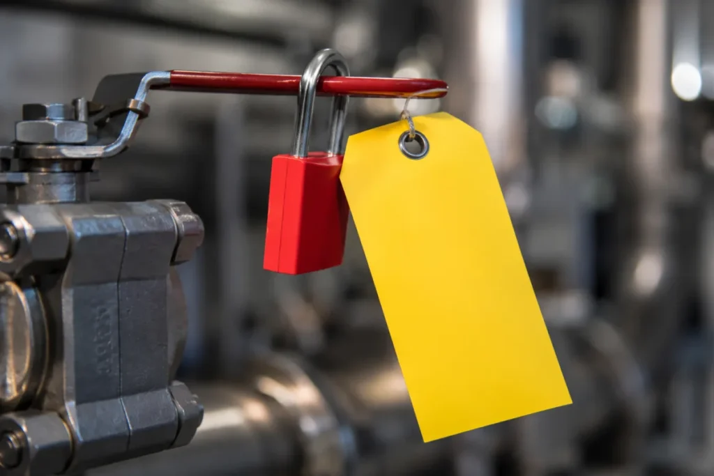
With that boundary set, here is how to get a 3-piece stainless steel ball valve installed correctly and keep it running.
Confirm the Valve Is Suitable Before Installation
A surprising share of “valve failures” are selection failures that only become visible after start-up. Before installation, and ideally before purchase, check the specific model’s datasheet against the actual service:
- Model and size, exactly as they appear on the datasheet, not as remembered from a similar valve.
- Material der Karosserie. For stainless ball valves this is typically 304 or 316. Chloride-bearing media generally point toward 316, whose molybdenum content improves resistance to pitting.
- Materialien für Sitze und Dichtungen. Standard soft seats are usually PTFE; confirm chemical and temperature suitability for your specific media.
- Endanschlüsse — thread standard, socket weld or butt weld, and the pipe standard they must match.
- Pressure–temperature rating for the combination you will actually run, not just the headline pressure class.
- Media details: composition, concentration, temperature range, and any entrained solids.
- Actuation and fail position, if the valve is automated: air or electric supply, and what the valve must do on loss of that supply.
A note on WOG ratings. WOG (water, oil, gas) is a cold, non-shock pressure rating. Our standard 3-piece stainless steel ball valves are rated 1000 WOG. That figure is a valid starting point for cold, steady, non-shock service. It is not, on its own, an approval for steam, elevated temperature, pressure pulsation or water hammer. Soft-seated valves derate as temperature rises, and each of those conditions has to be checked against the specific model’s pressure–temperature data. If you do not have that data, request it before ordering — the list in the final section of this article can be pasted straight into an RFQ.
Pre-Installation Checklist
- Keep the protective end caps on until the valve actually goes into the line. Seats damaged in storage or transport show up as leaks at commissioning.
- Clean the pipe first. Weld slag, mill scale, sand and thread chips left in a new line will scar soft seats within the first few operating cycles. Flush or blow the line before the valve is installed, or install with the valve removed from its center section where the design allows it.
- Support the pipe on both sides. The valve is not a structural member. Pipe weight, thermal movement or a joint pulled into forced alignment all preload the body joints and can distort sealing surfaces.
- Leave room to work. Check handle swing, clearance to remove an actuator, and enough axial and radial space to drop the center section out later. A 3-piece valve installed where the center section cannot come out has lost its main advantage.
- Check the required ball position for installation — particularly before welding — in the product’s installation instructions.
Installing Threaded, Flanged and Weld-End Valves
Threaded connections. Confirm that the valve and the pipe use the same thread standard. PT (taper) and NPT threads differ in form; a mixed joint may appear to engage but will not seal reliably. Check both sides before applying any sealant. The sealant itself is not a one-answer question: it must be compatible with the media and temperature, meet any cleanliness or regulatory requirements that apply (potable water, food contact, oxygen service), and follow the valve manufacturer’s instructions. There is no universal thread compound. When tightening, put the wrench on the end-cap flats nearest the joint being made — never across the valve body or handle.
Flanged connections. Select the gasket for the service, inspect flange faces for damage and cleanliness, and carry out bolt lubrication, tightening pattern and torque according to the applicable flange, gasket and bolting specification — bolted-joint assembly practice such as ASME PCC-1 exists for exactly this purpose. Flange bolting torque is a property of the joint, not of the valve, so take it from the joint specification rather than from a generic table.
Weld-end valves. Welding is where a butt-weld 3-piece valve earns its keep, and where the most expensive mistakes happen. Use qualified welders working to a qualified WPS (welding procedure specification). Whether the center section and seats must be removed before welding, or whether the design permits welding with the valve assembled, depends on the model and the weld type — socket weld and butt weld put different heat input near the seats. Follow the specific product’s installation instructions, and ask the supplier before striking an arc if they are unclear. After welding, let the joint cool naturally, flush the line to remove slag and debris, then reassemble and leak-test following the IOM’s procedure and its torque values. We deliberately give no generic welding parameters or bolt torques here; they belong to the model’s own documentation.
For a closer look at how the end connection types compare, see our guide to Ventilanschlüsse.
Routine 3-Piece Ball Valve Maintenance and Inspection
There is no universal inspection calendar for ball valves. The right interval is set by the media, operating temperature, differential pressure, cycle rate, corrosivity, solids content, and what a failure would cost or endanger. A valve cycling dozens of times a day on hot condensate and a cold-water isolation valve operated twice a year do not belong on the same schedule. Set intervals in your plant’s maintenance system, start conservative, and adjust based on what inspections actually find.
At each inspection, look at:
- External leakage at the stem and at both body joints.
- Operating torque. A valve that has become noticeably harder to turn is telling you something — do not extend the handle to overpower it.
- Actuator condition on automated valves: supply pressure, signal, full travel to both end positions, solenoid and limit switch function.
- Seat tightness, where the process allows it to be observed — for example pressure building downstream of a closed valve during an isolation.
- External corrosion, especially under insulation or in chloride-rich environments.
- Vibration and pipe support around the valve.
When seats, stem seals or body seals need replacement, use the repair kit specified for that model and follow the IOM’s disassembly, assembly and torque instructions — and only ever on a valve that has been isolated, depressurized and drained as described at the top of this article. If you do not have the IOM or a repair kit reference for a valve in the field, contact the supplier with the nameplate details rather than improvising.
Troubleshooting
| Symptom | Possible causes | First steps (after proper isolation, where work on the valve is needed) | Stop and contact the supplier when… |
|---|---|---|---|
| Stem leakage | Worn or relaxed stem seals; thermal cycling; scored stem surface; chemical attack on seal material. | Identify the media and hazard first. Isolate per procedure, then inspect the stem and seals. Any adjustment or replacement of stem seals follows the model’s IOM. | The leak returns after seal replacement, the stem is scored or corroded, or the media is hazardous enough that any external leak is unacceptable. |
| Body joint leakage | Damaged or aged body seals; joint disturbed during service work; bolt load relaxed by thermal cycling; seal material incompatible with media. | Isolate, open the joint, inspect the body seals and their sealing faces, and rebuild with the correct repair kit to the IOM’s torque values. Retightening bolts alone is not a reliable fix — if the seal or face is damaged, added bolt load will not seal it. | Leakage persists after new seals, or the sealing faces show corrosion, erosion or mechanical damage. |
| Internal seat leakage | Seat wear; debris scarring; thermal or chemical degradation of the seat; valve used to throttle when designed for on/off. | Confirm the valve is actually reaching full closed position. Then plan an isolation to inspect the ball and seats and replace seats with the model’s repair kit. | The ball surface is scratched, eroded or corroded, or the application needs verified tight shutoff for safety (consider double isolation instead of relying on one valve). |
| High operating torque | Dry or degraded seats; media deposits on the ball; long idle periods; corrosion at the stem; on automated valves, an undersized or failing actuator. | Do not force the valve with an extended handle. Check for process causes (deposits, temperature), and on automated valves verify supply pressure before blaming the valve. | Torque keeps rising over successive operations, or the valve sticks — internal inspection is needed. |
| Actuator does not reach end position | Low air supply pressure; solenoid, positioner or signal fault; travel stops misadjusted; valve torque above actuator output; debris obstructing the ball. | Verify supply pressure and signal, then check travel stop and limit switch settings against the actuator manual. | The actuator and supply check out but the valve still will not travel — the resistance is inside the valve. |
When a 3-Piece Valve Is the Right Choice
A 3-piece ball valve is a strong choice for on/off isolation duty where you want welded end connections for permanently tight joints, but still need to service the valve internals; for services that consume seats and seals on a known rhythm and justify planned rebuilds; and for plants where downtime is expensive enough that swapping a center section beats cutting pipe.
It is not a universal answer. Standard models are soft-seated, typically with PTFE, and that sets real limits: throttling duty, abrasive media, steam and elevated temperatures each require verification against the specific model’s datasheet, and some of those services are better served by metal-seated valves or a different valve type altogether. If your service involves any of them, say so at the inquiry stage — it is much cheaper to find out then.
Information to Include When Requesting Service or a Quote
Whether you are specifying new valves or asking about a repair kit for installed ones, this is the information that lets an engineering team give you a firm answer instead of a guess:
- Valve model and size (from the nameplate or datasheet)
- Body, seat and seal materials
- Media, including concentration and any solids
- Normal and maximum operating pressure and temperature
- Differential pressure across the valve at shutoff
- Cycle frequency (operations per day/week/year)
- End connection type and the pipe standard it must match
- Whether the service involves steam, thermal cycling or water hammer
- Actuation type and required fail position, if automated
- Documents you require: material certificates, test reports, dimensional drawings
Send these details to our team via the Kontaktseite and we can confirm which model fits your service — such as the 3-piece 1000 WOG series in threaded, socket-weld and butt-weld ends — or identify the correct repair kit for valves already in your plant.